Chapter 1 Product Overview
Hardware
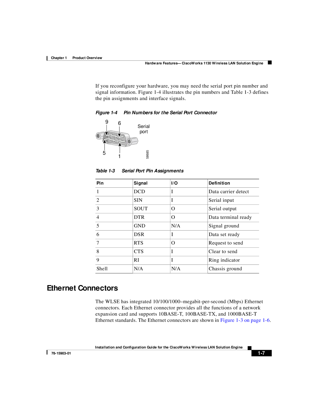
If you reconfigure your hardware, you may need the serial port pin number and signal information. Figure
Figure 1-4 Pin Numbers for the Serial Port Connector
9 6
5![]()
1
Serial
port
58685
Table
Pin | Signal | I/O | Definition |
|
|
|
|
1 | DCD | I | Data carrier detect |
|
|
|
|
2 | SIN | I | Serial input |
|
|
|
|
3 | SOUT | O | Serial output |
|
|
|
|
4 | DTR | O | Data terminal ready |
|
|
|
|
5 | GND | N/A | Signal ground |
|
|
|
|
6 | DSR | I | Data set ready |
|
|
|
|
7 | RTS | O | Request to send |
|
|
|
|
8 | CTS | I | Clear to send |
|
|
|
|
9 | RI | I | Ring indicator |
|
|
|
|
Shell | N/A | N/A | Chassis ground |
|
|
|
|
Ethernet Connectors
The WLSE has integrated
| Installation and Configuration Guide for the CiscoWorks Wireless LAN Solution Engine |