Chapter 2 - IP Routing & Bridging | 37 |
|
|
TCP/IP Routing: Bridge Configuration Dialog Box
IP Bridge Group
Port 0
Port 1
Port 2
Port 3
Multiport Router/Switch
IPX Bridge Group
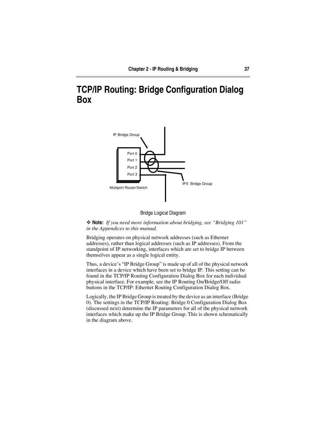
Bridge Logical Diagram
ϖNote: If you need more information about bridging, see “Bridging 101” in the Appendices to this manual.
Bridging operates on physical network addresses (such as Ethernet addresses), rather than logical addresses (such as IP addresses). From the standpoint of IP networking, interfaces which are set to bridge IP between themselves appear as a single logical entity.
Thus, a device’s “IP Bridge Group” is made up of all of the physical network interfaces in a device which have been set to bridge IP. This setting can be found in the TCP/IP Routing Configuration Dialog Box for each individual physical interface. For example, see the IP Routing On/Bridge/Off radio buttons in the TCP/IP: Ethernet Routing Configuration Dialog Box.
Logically, the IP Bridge Group is treated by the device as an interface (Bridge 0). The settings in the TCP/IP Routing: Bridge 0 Configuration Dialog Box (discussed next) determine the IP parameters for all of the physical network interfaces which make up the IP Bridge Group. This is shown schematically in the diagram above.
