Robot
Page
Preface
Robot models covered by this manual
How the documentation set is organized
Interface Manual this book
Describes I/O cables and wiring Iii
How this book is organized
Page
Safety Precautions
Should not be installed in any environment where
Structure. Therefore, when using the robot controller in an
Robot and peripheral equipment should be installed so that
Sufficient service space is maintained for safe teaching
Safety Precautions
Page
No robot modification allowed Cleaning of tools Lighting
Refer to the Installation & Maintenance Guide
Or maintenance inspections, set working regulations for
Operating procedures required to run the robot
Robot speed when performing teaching
Signaling methods to be used when more than one worker
Safety Precautions
Page
Management of floppy disks
Page
Contents
Dedicated to Standard Mode
100
Index
Controller Model Name on Nameplate
Coding of Controller Model Name
Position Code Denotes Coding Sample
How to identify your robot system as Type a
Deadman switches are located as shown below
Symbol denoting Type a
Internal Auto Limited Mode
External Auto Limited Mode
Setting the parameter
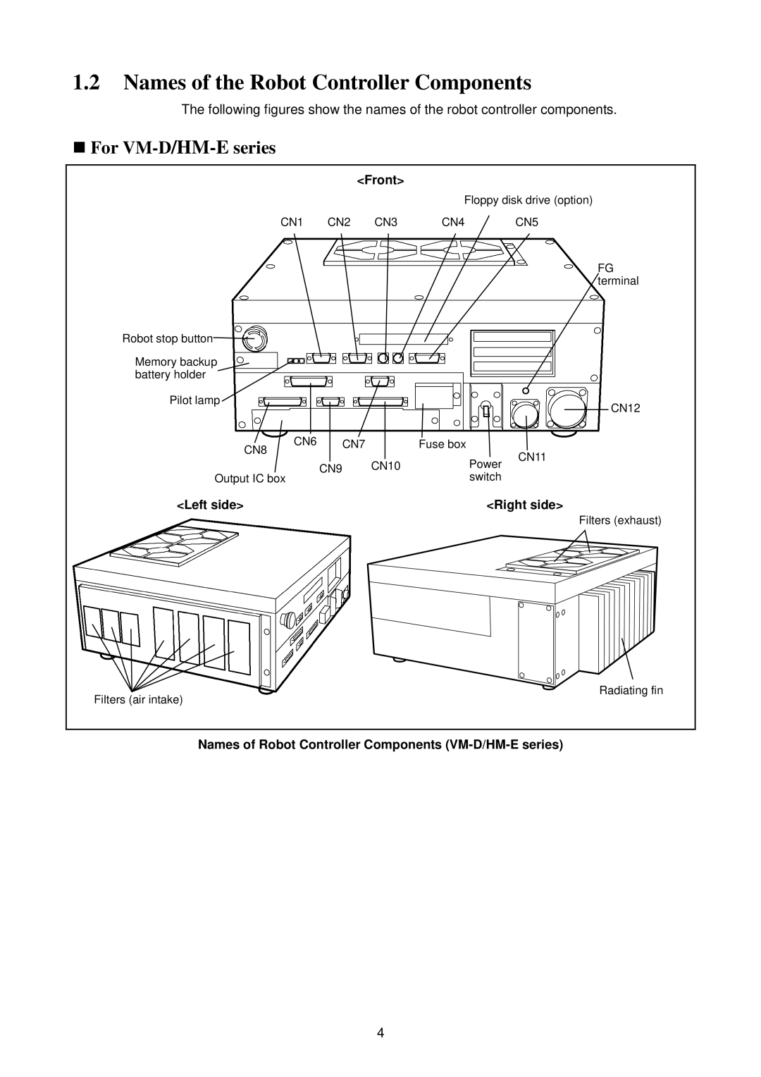
Names of the Robot Controller Components
Front
Left side Right side
Names of Robot Controller Components VM-D/HM-E series
For robot series except VM-D/HM-E
Connector Marking Name
Robot Controller Specifications
Table below lists the robot controller specifications
Robot Controller Specifications
Page
Outer Dimensions
Outer dimensions of the robot controller are shown below
Location of IPM boards
Series Location Models
Controller System Configuration
Internal Circuits of the Controller Typical configuration
Typical Robot System Configurations
Robot System Configuration
System Configuration Example
Standard Mode and Compatible Mode
Switching between Modes
I/O Monitor window appears
Auxiliary Functions I/O window appears as shown below
I/O assignment mode is switched
Choose allocation window appears as shown below
Following system message appears
Screen returns to the Auxiliary Functions I/O window
Computer
Section
GUIDE, , Section
Click on the DIO Manager button in the System Manager
Hardware settings will appear
Options window will appear as shown below
Options window closes
Connect button appears in a pressed state
Update the data
Transfer Environment Table window appears
I/O assignment mode is switched
Types and General Information about I/O Signals
Standard Mode
Compatible Mode
Compatibility with conventional VS series robots
Controlled by user program Type No. Function Points
Using User I/O Signals common to both modes
User Input Commands
1 I/O Type Variable Declaration
2 I/O Type Global Variables
User Output Commands
SET Command
System I/O Signals Standard Mode
Types and Functions of System Output Signals Standard Mode
Usage of System Output Signals Standard Mode
Robot Initialization Complete Output
Auto Mode Output
Auto mode Output
On condition
OFF conditions
External Mode Output
No.7 of connector CN10
External Mode Output
Terminal number
No.4 of connector CN10
Servo on Output
Servo on Output