Robot
Page
Preface
Robot models covered by this manual
How the documentation set is organized
Interface Manual this book
Describes I/O cables and wiring Iii
How this book is organized
Page
Safety Precautions
Robot and peripheral equipment should be installed so that
Should not be installed in any environment where
Structure. Therefore, when using the robot controller in an
Sufficient service space is maintained for safe teaching
Safety Precautions
Page
No robot modification allowed Cleaning of tools Lighting
Refer to the Installation & Maintenance Guide
Robot speed when performing teaching
Or maintenance inspections, set working regulations for
Operating procedures required to run the robot
Signaling methods to be used when more than one worker
Safety Precautions
Page
Management of floppy disks
Page
Contents
Dedicated to Standard Mode
100
Index
Coding of Controller Model Name
Controller Model Name on Nameplate
Position Code Denotes Coding Sample
Deadman switches are located as shown below
How to identify your robot system as Type a
Symbol denoting Type a
External Auto Limited Mode
Internal Auto Limited Mode
Setting the parameter
Left side Right side
Names of the Robot Controller Components
Front
Names of Robot Controller Components VM-D/HM-E series
For robot series except VM-D/HM-E
Connector Marking Name
Table below lists the robot controller specifications
Robot Controller Specifications
Robot Controller Specifications
Page
Outer Dimensions
Outer dimensions of the robot controller are shown below
Location of IPM boards
Series Location Models
Controller System Configuration
Internal Circuits of the Controller Typical configuration
Typical Robot System Configurations
Robot System Configuration
System Configuration Example
Standard Mode and Compatible Mode
Switching between Modes
I/O Monitor window appears
Auxiliary Functions I/O window appears as shown below
Following system message appears
I/O assignment mode is switched
Choose allocation window appears as shown below
Screen returns to the Auxiliary Functions I/O window
GUIDE, , Section
Computer
Section
Click on the DIO Manager button in the System Manager
Hardware settings will appear
Options window will appear as shown below
Options window closes
Connect button appears in a pressed state
Update the data
Transfer Environment Table window appears
I/O assignment mode is switched
Types and General Information about I/O Signals
Standard Mode
Compatibility with conventional VS series robots
Compatible Mode
Controlled by user program Type No. Function Points
1 I/O Type Variable Declaration
Using User I/O Signals common to both modes
User Input Commands
2 I/O Type Global Variables
User Output Commands
SET Command
System I/O Signals Standard Mode
Types and Functions of System Output Signals Standard Mode
Usage of System Output Signals Standard Mode
Robot Initialization Complete Output
On condition
Auto Mode Output
Auto mode Output
OFF conditions
External Mode Output
External Mode Output
No.7 of connector CN10
Terminal number
Servo on Output
No.4 of connector CN10
Servo on Output
Signal will be turned OFF with Stop ALL Programs
Robot-in-operation Output
Normal CPU Output
Normal CPU Output
Robot Failure Output
Robot Failure Output
Robot Warning Output
Robot Warning Output
Dead Battery Warning Output
Dead Battery Warning Output
This signal comes on when the SS mode is selected
SS mode Output
Continue Start Permitted Output
Emergency Stop Output from a contact
No of connector CN10 Emergency stop +
Contact
Types and Functions of System Input Signals Standard Mode
No of connector CN8
Usage of System Input Signals Standard Mode
Enable Auto Input
Relationship Between Enable Auto Input and Selectable Mode
Robot Stop Input
Timing of the input
Step Stop All Tasks Input
No.5 of connector CN8
Step Stop Signal
Terminal
Instantaneous Stop All Tasks Input
Minimum Instantaneous Stop Pulse Width
See the Programmers Manual I, , 12.3 Interrupt ON/OFF
Terminal number No.9 of connector CN8
Interrupt Skip Input
Input Conditions and Operation of Interrupt Skip
Example of Operation When an Interrupt Skip is Input
Wrong
Table below shows the I/O commands functions
General Information about Commands
Command Functions
Commands to be executed are processed as shown below
Outline of I/O Command Processing
Page
Using Each Signal Line
Terminal numbers
Strobe Signal Input
Command Processing Complete Output
No of connector CN10
Nos to 32 of connector CN10
Status Area
Table below lists I/O commands
3 I/O Commands Details List of I/O Commands
List of I/O Commands
Format
Program Operation Command
Description
Page
Page
External Speed and Acceleration Setting
Hexadecimal codes
Error Read
Example of Error Number Output
Refer to the figure given below
Type I Variable Write
Type I Variable Read
Mode Switching
Page
This command clears a robot failure that has been caused
Clear Robot Failure
3.9 I/O Write
3.10 I/O Read
Equipment setup example
Example of Using System I/O Signals in Standard Mode
Example of Equipment Setup Using a Robot
Outline of procedure
Start and stop procedure, and system I/O signals
Start and Stop Procedure and System I/O Signals-1
On following
From preceding
END
System I/O Signals Compatible Mode
Usage of System Output Signals in the Compatible Mode
Robot Power on Complete
Teach Check
⋅ MOTORu OFv F
CAL Complete Output
Signal outputs to the external device that CAL is completed
CAL Complete Output
External Mode Output
Teaching Output
Teaching Output
Program Start Reset Output
Program Start Reset Output on Condition
Program will be turned OFF with Stop ALL Programs
Single-Cycle End Output
Single-Cycle End Output
Normal CPU Output
Operated. Cancelu ƒv L ‘ € ì
Robot Warning Output
Power on
Signal will be output when an error occurs
Error No. Output
No.17 to No.28 of connector CN10
Clear conditions
Continue Start Permitted Output
Emergency Stop Output from a contact
Types and Functions of System Input Signals Compatible Mode
Usage of System Input Signals in Compatible Mode
OFF
Motor power on input
Operation Preparation Start Input
Example of Operation Preparation Start Signal Timing Chart
Program No. Select Signal
No.11 to No.18 of connector CN8
Program No. Select Input
Example of Program No. Select Signals
Example of Program No. Select Signal Sequence Circuit
Program Start Input
Program Start Operation-1
Program Start Operation-2
Program Start Operation-3
Example of program start signal rise on and fall OFF timing
Example of Program Start Signal Rise Timing
Example of Program Start Signal Fall Timing-1
Example of Program Start Signal Fall Timing-2
Program Start Signal Rise Output Signal Timing
Program Reset Input
Input Conditions and Operation of Program Reset Signal
When issued with the Operation Preparation Start
Input timing
101
102
Clear Robot Failure Input
103
Refer to the Programmers Manual I
104
Example of Operation When an Interrupt Skip Signal is Input
Continue Start Input
Example of Using System I/O Signals in Compatible Mode
106
Start and stop procedure and system I/O signals
On the next 108
109
Signal
Operation Preparation Start Input
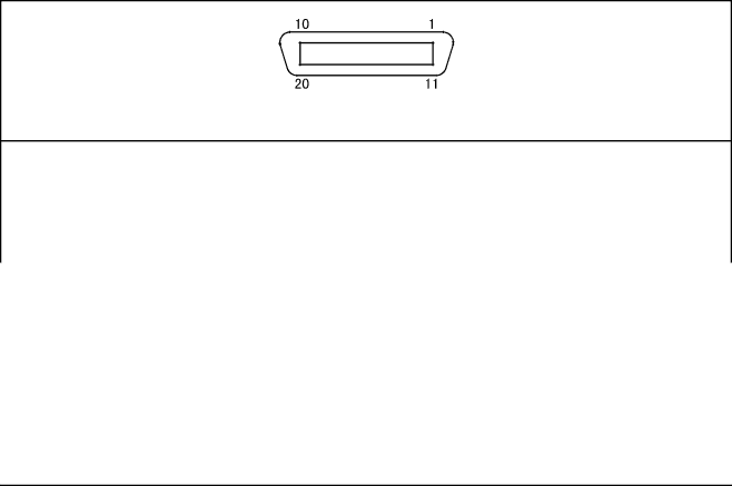
Connector Pin Assignment Common to Both Modes NPN type
Connector Pin Assignment NPN type
110
111
CN1 Pin Assignment Terminal No Name
Output CN10 User-/System-output connector standard mode
Connector Pin Assignment in Standard Mode
112
Input CN8 User-/System-input connector standard mode
113
Output CN10 User-/System-output connector compatible mode
Connector Pin Assignment in Compatible Mode
114
Input CN8 User-/System-input connector compatible mode
115
User-Input, System-Input and Hand-Input Circuits NPN type
Robot Controller I/O Circuits NPN type
116
117
118
Robot Stop and Enable Auto Input Circuits
Robot Stop and Enable Auto Input Circuits
120
121
122
123
Example of Circuit with Lamp NPN type
Standard type
When the internal power source is used
Emergency Stop Circuit
124
125
Dual emergency stop type
Emergency Stop Circuit Dual emergency stop type
5 I/O Power Connector NPN type
126
127
128
Wiring Notes for Robot Controller I/O Connectors NPN Type
Checking Example
129
Name Meaning Check Number Point
Connector Pin Assignment Common to Both Modes PNP type
Connector Pin Assignment PNP type
130
O Power CN7 Power connector for I/O common to both modes
131
Terminal Number Name Port Wire Color Port Wire number color
132
Input CN8 User-/System-input connector standard mode
133
134
135
#26, #2 and #27,…#25 and #50
User-Input, System-Input and Hand-Input Circuits PNP type
Robot Controller I/O Circuits PNP type
136
137
138
Robot Stop and Enable Auto Input Circuits
140
141
142
143
Example of Circuit with Lamp PNP type
144
145
5 I/O Power Connector PNP type
146
147
Wiring Notes for Robot Controller I/O Connectors PNP Type
148
149
150
Multi-core Cables with Connectors
Cables Optional items
Modifying the Shielding Wire Example
151
Wiring of Primary Power Source
Robot Controller Power Supply Specifications
Index
Servo on Output
First Edition
Second Edition June