Chapter 5 Parameter Definitions
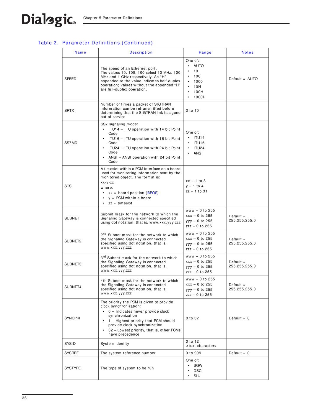
Table 2. Parameter Definitions (Continued)
Name | Description |
| Range | Notes | |
|
|
|
| ||
|
| One of: |
| ||
| The speed of an Ethernet port. | • | AUTO |
| |
| • | 10 |
| ||
| The values 10, 100, 100 select 10 MHz, 100 |
| |||
| • | 100 |
| ||
SPEED | MHz and 1 GHz respectively. An “H” | Default = AUTO | |||
appended to the value indicates | • | 1000 | |||
|
| ||||
| operation; values without the appended “H” | • | 10H |
| |
| are |
| |||
| • | 100H |
| ||
|
|
| |||
|
| • | 1000H |
| |
|
|
|
|
| |
| Number of times a packet of SIGTRAN |
|
|
| |
SRTX | information can be retransmitted before | 2 to 10 |
| ||
determining that the SIGTRAN link has gone |
| ||||
|
|
|
| ||
| out of service |
|
|
| |
|
|
|
|
| |
| SS7 signaling mode: |
|
|
| |
| • ITU14 – ITU operation with 14 bit Point | One of: |
| ||
| Code |
| |||
SS7MD | • ITU16 – ITU operation with 16 bit Point | • | ITU14 |
| |
Code | • | ITU16 |
| ||
| • ITU24 – ITU operation with 24 bit Point | • | ITU24 |
| |
| Code | • | ANSI |
| |
| • ANSI – ANSI operation with 24 bit Point |
|
|
| |
| Code |
|
|
| |
|
|
|
|
| |
| A timeslot within a PCM interface on a board |
|
|
| |
| used for monitoring information sent by the |
|
|
| |
| monitored object. The format is: | xx – 1 to 3 |
| ||
|
| ||||
STS | y – 1 to 4 |
| |||
where: |
| ||||
| zz – 1 to 31 |
| |||
| • xx = board position (BPOS) |
| |||
|
|
|
| ||
| • y = PCM within a board |
|
|
| |
| • zz = timeslot |
|
|
| |
|
|
|
| ||
| Subnet mask for the network to which the | www – 0 to 255 |
| ||
| xxx – 0 to 255 | Default = | |||
SUBNET | Signaling Gateway is connected specified | ||||
yyy – 0 to 255 | 255.255.255.0 | ||||
| using dot notation, that is, www.xxx.yyy.zzz | ||||
| zzz – 0 to 255 |
| |||
|
|
| |||
|
|
|
| ||
| 2nd Subnet mask for the network to which | www – 0 to 255 |
| ||
SUBNET2 | the Signaling Gateway is connected | xxx – 0 to 255 | Default = | ||
specified using dot notation, that is, | yyy – 0 to 255 | 255.255.255.0 | |||
| |||||
| www.xxx.yyy.zzz | zzz – 0 to 255 |
| ||
|
|
| |||
|
|
|
| ||
| 3rd Subnet mask for the network to which | www – 0 to 255 |
| ||
SUBNET3 | the Signaling Gateway is connected | xxx – 0 to 255 | Default = | ||
specified using dot notation, that is, | yyy – 0 to 255 | 255.255.255.0 | |||
| |||||
| www.xxx.yyy.zzz | zzz – 0 to 255 |
| ||
|
|
| |||
|
|
|
| ||
| 4th Subnet mask for the network to which | www – 0 to 255 |
| ||
| xxx – 0 to 255 |
| |||
SUBNET4 | the Signaling Gateway is connected | Default = | |||
specified using dot notation, that is, | yyy – 0 to 255 | 255.255.255.0 | |||
| |||||
| www.xxx.yyy.zzz | zzz – 0 to 255 |
| ||
|
|
| |||
|
|
|
|
| |
| The priority the PCM is given to provide |
|
|
| |
| clock synchronization: |
|
|
| |
| • 0 – Indicates never provide clock |
|
|
| |
SYNCPRI | synchronization | 0 to 32 | Default = 0 | ||
• 1 – Highest priority that PCM should | |||||
|
|
|
| ||
| provide clock synchronization |
|
|
| |
| • 32 – Lowest priority, that is, other PCMs |
|
|
| |
| have precedence |
|
|
| |
|
|
|
| ||
SYSID | System identity | 0 to 12 |
| ||
<text character> |
| ||||
|
|
| |||
|
|
|
| ||
SYSREF | The system reference number | 0 to 999 | Default = 0 | ||
|
|
|
| ||
|
| One of: |
| ||
SYSTYPE | The type of system to be run | • | SGW |
| |
• | DSC |
| |||
|
|
| |||
|
| • | SIU |
| |
|
|
|
|
| |
36