Dialogic® SS7G2x Signaling Server SGW Mode User Manual Issue 4
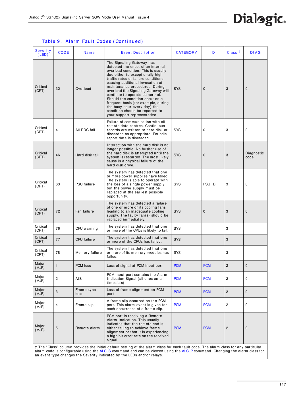
Table 9. Alarm Fault Codes (Continued)
Severity | CODE | Name | Event Description | CATEGORY | ID | Class † | DIAG | |
(LED) |
|
|
|
|
|
|
| |
|
|
|
|
|
|
|
| |
|
|
| The Signaling Gateway has |
|
|
|
| |
|
|
| detected the onset of an internal |
|
|
|
| |
|
|
| overload condition. This is usually |
|
|
|
| |
|
|
| due either to exceptionally high |
|
|
|
| |
|
|
| traffic rates or failure conditions |
|
|
|
| |
|
|
| causing additional invocation of |
|
|
|
| |
Critical | 32 | Overload | maintenance procedures. During | SYS | 0 | 3 | 0 | |
(CRT) | overload the Signaling Gateway will | |||||||
|
|
|
|
|
| |||
|
|
| continue to operate as normal. |
|
|
|
| |
|
|
| Should the condition occur on a |
|
|
|
| |
|
|
| frequent basis (for example, during |
|
|
|
| |
|
|
| the busy hour every day) the |
|
|
|
| |
|
|
| condition should be reported to |
|
|
|
| |
|
|
| your support representative. |
|
|
|
| |
|
|
|
|
|
|
|
| |
|
|
| Failure of communication with all |
|
|
|
| |
Critical |
|
| remote data centres. Continuous |
|
|
|
| |
41 | All RDC fail | records are written to hard disk or | SYS | 0 | 3 | 0 | ||
(CRT) | ||||||||
|
| discarded as appropriate. Periodic |
|
|
|
| ||
|
|
|
|
|
|
| ||
|
|
| report data is discarded. |
|
|
|
| |
|
|
|
|
|
|
|
| |
|
|
| Interaction with the hard disk is no |
|
|
|
| |
Critical |
|
| longer possible. No further use of |
|
|
| Diagnostic | |
46 | Hard disk fail | the hard disk is attempted until the | SYS | 0 | 3 | |||
(CRT) | system is restarted. The most likely | code | ||||||
|
|
|
|
| ||||
|
|
| cause is a physical failure of the |
|
|
|
| |
|
|
| hard disk drive. |
|
|
|
| |
|
|
|
|
|
|
|
| |
|
|
| The system has detected that one |
|
|
|
| |
|
|
| or more power supplies have failed. |
|
|
|
| |
Critical |
|
| The system is able to operate with |
|
|
|
| |
63 | PSU failure | the loss of a single power supply | SYS | PSU ID | 3 | 0 | ||
(CRT) | ||||||||
|
| but the power supply must be |
|
|
|
| ||
|
|
|
|
|
|
| ||
|
|
| replaced at the earliest possible |
|
|
|
| |
|
|
| opportunity. |
|
|
|
| |
|
|
|
|
|
|
|
| |
|
|
| The system has detected a failure |
|
|
|
| |
Critical |
|
| of one or more or its cooling fans |
|
|
|
| |
72 | Fan failure | leading to an inadequate cooling | SYS | 0 | 3 | 0 | ||
(CRT) | ||||||||
|
| supply. The faulty fan(s) should be |
|
|
|
| ||
|
|
|
|
|
|
| ||
|
|
| replaced immediately. |
|
|
|
| |
|
|
|
|
|
|
|
| |
Critical | 76 | CPU warning | The system has detected that one | SYS |
| 3 |
| |
(CRT) | or more of the CPUs is likely to fail. |
|
| |||||
|
|
|
|
|
| |||
|
|
|
|
|
|
|
| |
Critical | 77 | CPU failure | The system has detected that one | SYS |
| 3 |
| |
(CRT) | or more of the CPUs has failed. |
|
| |||||
|
|
|
|
|
| |||
|
|
|
|
|
|
|
| |
Critical |
|
| The system has detected that one |
|
|
|
| |
78 | Memory failure | or more of its memory modules has | SYS |
| 3 |
| ||
(CRT) |
|
| ||||||
|
| failed. |
|
|
|
| ||
|
|
|
|
|
|
| ||
|
|
|
|
|
|
|
| |
Major | 1 | PCM loss | Loss of signal at PCM input port | PCM | PCM | 2 | 0 | |
(MJR) | ||||||||
|
|
|
|
|
|
| ||
|
|
|
|
|
|
|
| |
Major |
|
| PCM input port contains the Alarm |
|
|
|
| |
2 | AIS | Indication Signal (all ones on all | PCM | PCM | 2 | 0 | ||
(MJR) | ||||||||
|
| timeslots) |
|
|
|
| ||
|
|
|
|
|
|
| ||
|
|
|
|
|
|
|
| |
Major | 3 | Frame sync | Loss of frame alignment on PCM | PCM | PCM | 2 | 0 | |
(MJR) | loss | port | ||||||
|
|
|
|
| ||||
|
|
|
|
|
|
|
| |
Major |
|
| A frame slip occurred on the PCM |
|
|
|
| |
4 | Frame slip | port. This alarm event is given for | PCM | PCM | 2 | 0 | ||
(MJR) | ||||||||
|
| each occurrence of a frame slip. |
|
|
|
| ||
|
|
|
|
|
|
| ||
|
|
|
|
|
|
|
| |
|
|
| PCM port is receiving a Remote |
|
|
|
| |
|
|
| Alarm Indication. This usually |
|
|
|
| |
Major | 5 | Remote alarm | indicates that the remote end is | PCM | PCM | 2 | 0 | |
either failing to achieve frame | ||||||||
(MJR) | ||||||||
|
| alignment or that it is experiencing |
|
|
|
| ||
|
|
|
|
|
|
| ||
|
|
| a high bit error rate on the received |
|
|
|
| |
|
|
| signal. |
|
|
|
| |
|
|
|
|
|
|
|
|
†The “Class” column provides the initial default setting of the alarm class for each fault code. The alarm class for any particular alarm code is configurable using the ALCLS command and can be viewed using the ALCLP command. Changing the alarm class for an event type changes the Severity indicated by the LEDs and/or relays.
147