Dialogic® SS7G2x Signaling Server SGW Mode User Manual Issue 4
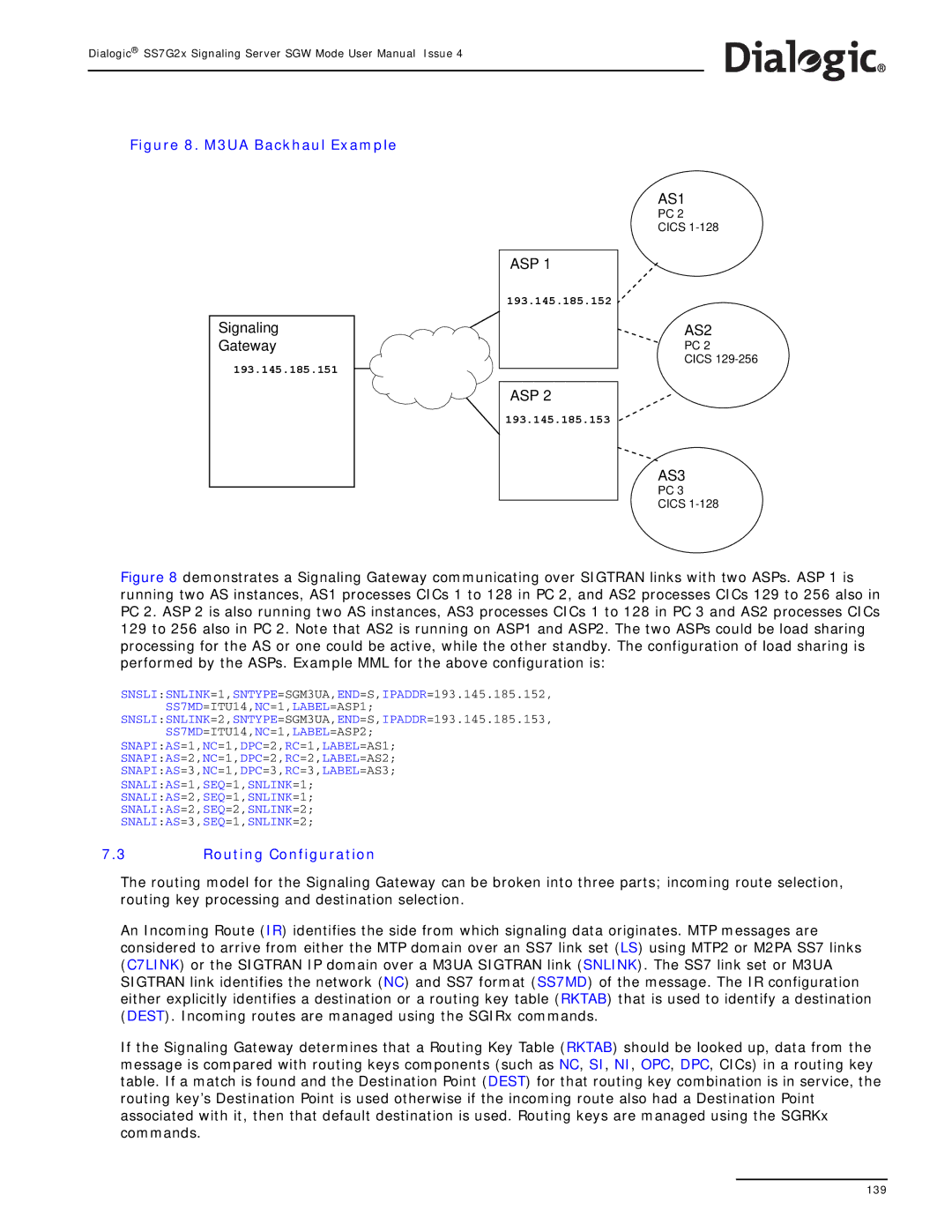
Figure 8. M3UA Backhaul Example
Signaling
Gateway
193.145.185.151
ASP 1
193.145.185.152
ASP 2
193.145.185.153
AS1
PC 2
CICS
AS2
PC 2
CICS
AS3
PC 3
CICS
Figure 8 demonstrates a Signaling Gateway communicating over SIGTRAN links with two ASPs. ASP 1 is running two AS instances, AS1 processes CICs 1 to 128 in PC 2, and AS2 processes CICs 129 to 256 also in PC 2. ASP 2 is also running two AS instances, AS3 processes CICs 1 to 128 in PC 3 and AS2 processes CICs 129 to 256 also in PC 2. Note that AS2 is running on ASP1 and ASP2. The two ASPs could be load sharing processing for the AS or one could be active, while the other standby. The configuration of load sharing is performed by the ASPs. Example MML for the above configuration is:
SNSLI:SNLINK=1,SNTYPE=SGM3UA,END=S,IPADDR=193.145.185.152,
SS7MD=ITU14,NC=1,LABEL=ASP1;
SNSLI:SNLINK=2,SNTYPE=SGM3UA,END=S,IPADDR=193.145.185.153,
SS7MD=ITU14,NC=1,LABEL=ASP2;
SNAPI:AS=1,NC=1,DPC=2,RC=1,LABEL=AS1;
SNAPI:AS=2,NC=1,DPC=2,RC=2,LABEL=AS2;
SNAPI:AS=3,NC=1,DPC=3,RC=3,LABEL=AS3;
SNALI:AS=1,SEQ=1,SNLINK=1;
SNALI:AS=2,SEQ=1,SNLINK=1;
SNALI:AS=2,SEQ=2,SNLINK=2;
SNALI:AS=3,SEQ=1,SNLINK=2;
7.3Routing Configuration
The routing model for the Signaling Gateway can be broken into three parts; incoming route selection, routing key processing and destination selection.
An Incoming Route (IR) identifies the side from which signaling data originates. MTP messages are considered to arrive from either the MTP domain over an SS7 link set (LS) using MTP2 or M2PA SS7 links (C7LINK) or the SIGTRAN IP domain over a M3UA SIGTRAN link (SNLINK). The SS7 link set or M3UA SIGTRAN link identifies the network (NC) and SS7 format (SS7MD) of the message. The IR configuration either explicitly identifies a destination or a routing key table (RKTAB) that is used to identify a destination (DEST). Incoming routes are managed using the SGIRx commands.
If the Signaling Gateway determines that a Routing Key Table (RKTAB) should be looked up, data from the message is compared with routing keys components (such as NC, SI, NI, OPC, DPC, CICs) in a routing key table. If a match is found and the Destination Point (DEST) for that routing key combination is in service, the routing key’s Destination Point is used otherwise if the incoming route also had a Destination Point associated with it, then that default destination is used. Routing keys are managed using the SGRKx commands.
139