Chapter 8 Alarm Fault Code Listing
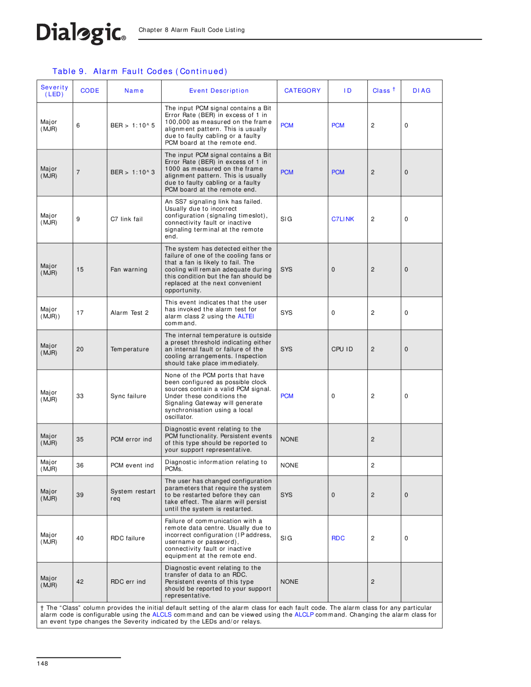
Table 9. Alarm Fault Codes (Continued)
Severity | CODE | Name | Event Description | CATEGORY | ID | Class † | DIAG | |
(LED) |
|
|
|
|
|
|
| |
|
|
|
|
|
|
|
| |
|
|
| The input PCM signal contains a Bit |
|
|
|
| |
|
|
| Error Rate (BER) in excess of 1 in |
|
|
|
| |
Major | 6 | BER > 1:10^5 | 100,000 as measured on the frame | PCM | PCM | 2 | 0 | |
(MJR) | alignment pattern. This is usually | |||||||
|
|
|
|
|
| |||
|
|
| due to faulty cabling or a faulty |
|
|
|
| |
|
|
| PCM board at the remote end. |
|
|
|
| |
|
|
|
|
|
|
|
| |
|
|
| The input PCM signal contains a Bit |
|
|
|
| |
|
|
| Error Rate (BER) in excess of 1 in |
|
|
|
| |
Major | 7 | BER > 1:10^3 | 1000 as measured on the frame | PCM | PCM | 2 | 0 | |
(MJR) | alignment pattern. This is usually | |||||||
|
|
|
|
|
| |||
|
|
| due to faulty cabling or a faulty |
|
|
|
| |
|
|
| PCM board at the remote end. |
|
|
|
| |
|
|
|
|
|
|
|
| |
|
|
| An SS7 signaling link has failed. |
|
|
|
| |
|
|
| Usually due to incorrect |
|
|
|
| |
Major | 9 | C7 link fail | configuration (signaling timeslot), | SIG | C7LINK | 2 | 0 | |
(MJR) | connectivity fault or inactive | |||||||
|
|
|
|
|
| |||
|
|
| signaling terminal at the remote |
|
|
|
| |
|
|
| end. |
|
|
|
| |
|
|
|
|
|
|
|
| |
|
|
| The system has detected either the |
|
|
|
| |
|
|
| failure of one of the cooling fans or |
|
|
|
| |
Major | 15 | Fan warning | that a fan is likely to fail. The | SYS | 0 | 2 | 0 | |
cooling will remain adequate during | ||||||||
(MJR) | ||||||||
|
| this condition but the fan should be |
|
|
|
| ||
|
|
|
|
|
|
| ||
|
|
| replaced at the next convenient |
|
|
|
| |
|
|
| opportunity. |
|
|
|
| |
|
|
|
|
|
|
|
| |
|
|
| This event indicates that the user |
|
|
|
| |
Major | 17 | Alarm Test 2 | has invoked the alarm test for | SYS | 0 | 2 | 0 | |
(MJR)) | alarm class 2 using the ALTEI | |||||||
|
|
|
|
|
| |||
|
|
| command. |
|
|
|
| |
|
|
|
|
|
|
|
| |
|
|
| The internal temperature is outside |
|
|
|
| |
Major |
|
| a preset threshold indicating either |
|
|
|
| |
20 | Temperature | an internal fault or failure of the | SYS | CPU ID | 2 | 0 | ||
(MJR) | ||||||||
|
| cooling arrangements. Inspection |
|
|
|
| ||
|
|
|
|
|
|
| ||
|
|
| should take place immediately. |
|
|
|
| |
|
|
|
|
|
|
|
| |
|
|
| None of the PCM ports that have |
|
|
|
| |
|
|
| been configured as possible clock |
|
|
|
| |
Major |
|
| sources contain a valid PCM signal. |
|
|
|
| |
33 | Sync failure | Under these conditions the | PCM | 0 | 2 | 0 | ||
(MJR) | ||||||||
|
| Signaling Gateway will generate |
|
|
|
| ||
|
|
|
|
|
|
| ||
|
|
| synchronisation using a local |
|
|
|
| |
|
|
| oscillator. |
|
|
|
| |
|
|
|
|
|
|
|
| |
Major |
|
| Diagnostic event relating to the |
|
|
|
| |
35 | PCM error ind | PCM functionality. Persistent events | NONE |
| 2 |
| ||
(MJR) | of this type should be reported to |
|
| |||||
|
|
|
|
|
| |||
|
|
| your support representative. |
|
|
|
| |
|
|
|
|
|
|
|
| |
Major | 36 | PCM event ind | Diagnostic information relating to | NONE |
| 2 |
| |
(MJR) | PCMs. |
|
| |||||
|
|
|
|
|
| |||
|
|
|
|
|
|
|
| |
|
|
| The user has changed configuration |
|
|
|
| |
Major | 39 | System restart | parameters that require the system | SYS | 0 | 2 | 0 | |
to be restarted before they can | ||||||||
(MJR) | req | |||||||
| take effect. The alarm will persist |
|
|
|
| |||
|
|
|
|
|
|
| ||
|
|
| until the system is restarted. |
|
|
|
| |
|
|
|
|
|
|
|
| |
|
|
| Failure of communication with a |
|
|
|
| |
Major |
|
| remote data centre. Usually due to |
|
|
|
| |
40 | RDC failure | incorrect configuration (IP address, | SIG | RDC | 2 | 0 | ||
(MJR) | username or password), | |||||||
|
|
|
|
|
| |||
|
|
| connectivity fault or inactive |
|
|
|
| |
|
|
| equipment at the remote end. |
|
|
|
| |
|
|
|
|
|
|
|
| |
|
|
| Diagnostic event relating to the |
|
|
|
| |
Major | 42 | RDC err ind | transfer of data to an RDC. | NONE |
| 2 |
| |
Persistent events of this type |
|
| ||||||
(MJR) |
|
| ||||||
|
| should be reported to your support |
|
|
|
| ||
|
|
|
|
|
|
| ||
|
|
| representative. |
|
|
|
| |
|
|
|
|
|
|
|
|
† The “Class” column provides the initial default setting of the alarm class for each fault code. The alarm class for any particular alarm code is configurable using the ALCLS command and can be viewed using the ALCLP command. Changing the alarm class for an event type changes the Severity indicated by the LEDs and/or relays.
148