Chapter 11 Worked Configuration Examples
Chapter 11: Worked Configuration Examples
11.1Backhaul Configuration
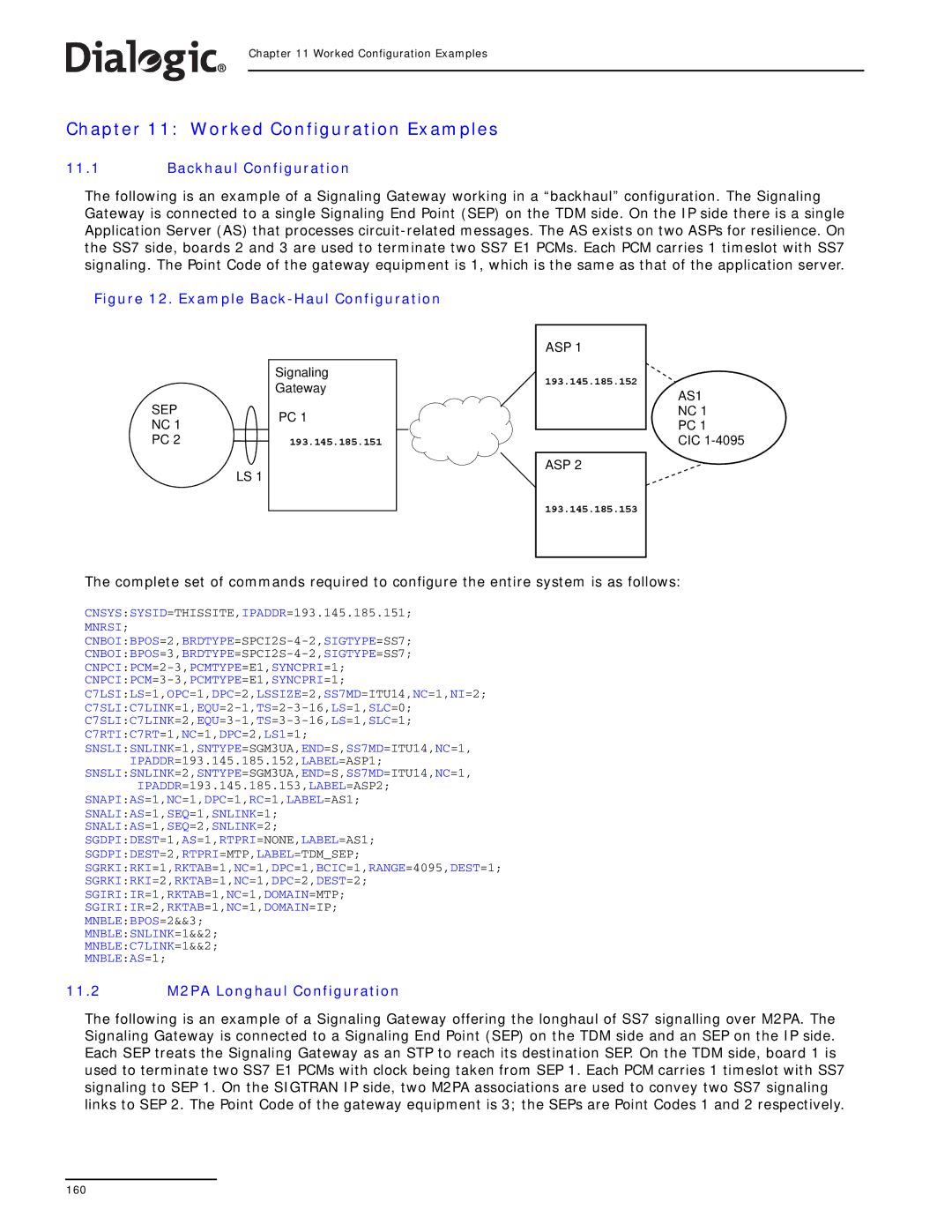
The following is an example of a Signaling Gateway working in a “backhaul” configuration. The Signaling Gateway is connected to a single Signaling End Point (SEP) on the TDM side. On the IP side there is a single Application Server (AS) that processes
Figure 12. Example Back-Haul Configuration
| Signaling | |
| Gateway | |
SEP | PC 1 | |
NC 1 | ||
| ||
PC 2 | 193.145.185.151 | |
| LS 1 |
ASP 1
193.145.185.152
ASP 2
AS1
NC 1
PC 1
CIC
193.145.185.153
The complete set of commands required to configure the entire system is as follows:
CNSYS:SYSID=THISSITE,IPADDR=193.145.185.151;
MNRSI;
C7LSI:LS=1,OPC=1,DPC=2,LSSIZE=2,SS7MD=ITU14,NC=1,NI=2;
C7RTI:C7RT=1,NC=1,DPC=2,LS1=1;
SNSLI:SNLINK=1,SNTYPE=SGM3UA,END=S,SS7MD=ITU14,NC=1,
IPADDR=193.145.185.152,LABEL=ASP1;
SNSLI:SNLINK=2,SNTYPE=SGM3UA,END=S,SS7MD=ITU14,NC=1,
IPADDR=193.145.185.153,LABEL=ASP2;
SNAPI:AS=1,NC=1,DPC=1,RC=1,LABEL=AS1;
SNALI:AS=1,SEQ=1,SNLINK=1;
SNALI:AS=1,SEQ=2,SNLINK=2;
SGDPI:DEST=1,AS=1,RTPRI=NONE,LABEL=AS1;
SGDPI:DEST=2,RTPRI=MTP,LABEL=TDM_SEP;
SGRKI:RKI=1,RKTAB=1,NC=1,DPC=1,BCIC=1,RANGE=4095,DEST=1;
SGRKI:RKI=2,RKTAB=1,NC=1,DPC=2,DEST=2;
SGIRI:IR=1,RKTAB=1,NC=1,DOMAIN=MTP;
SGIRI:IR=2,RKTAB=1,NC=1,DOMAIN=IP;
MNBLE:BPOS=2&&3;
MNBLE:SNLINK=1&&2;
MNBLE:C7LINK=1&&2;
MNBLE:AS=1;
11.2M2PA Longhaul Configuration
The following is an example of a Signaling Gateway offering the longhaul of SS7 signalling over M2PA. The Signaling Gateway is connected to a Signaling End Point (SEP) on the TDM side and an SEP on the IP side. Each SEP treats the Signaling Gateway as an STP to reach its destination SEP. On the TDM side, board 1 is used to terminate two SS7 E1 PCMs with clock being taken from SEP 1. Each PCM carries 1 timeslot with SS7 signaling to SEP 1. On the SIGTRAN IP side, two M2PA associations are used to convey two SS7 signaling links to SEP 2. The Point Code of the gateway equipment is 3; the SEPs are Point Codes 1 and 2 respectively.
160