Dialogic® SS7G2x Signaling Server SGW Mode User Manual Issue 4
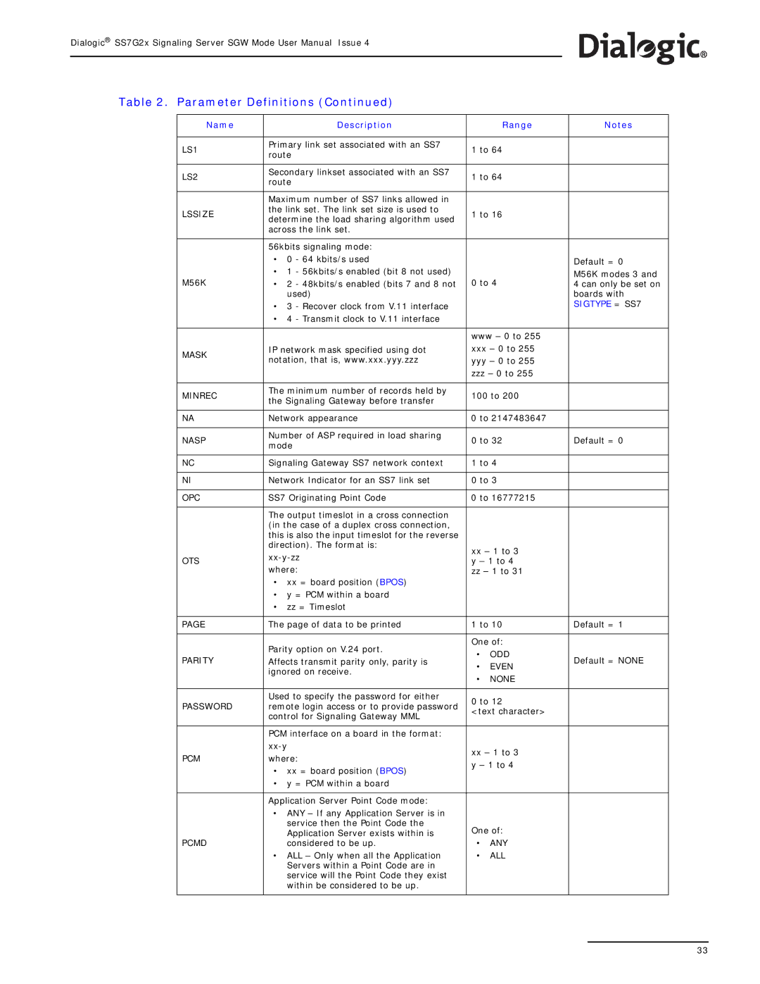
Table 2. Parameter Definitions (Continued)
Name |
| Description |
| Range | Notes | |
|
|
|
|
| ||
LS1 | Primary link set associated with an SS7 | 1 to 64 |
| |||
route |
| |||||
|
|
|
| |||
|
|
|
|
| ||
LS2 | Secondary linkset associated with an SS7 | 1 to 64 |
| |||
route |
| |||||
|
|
|
| |||
|
|
|
|
| ||
| Maximum number of SS7 links allowed in |
|
|
| ||
LSSIZE | the link set. The link set size is used to | 1 to 16 |
| |||
determine the load sharing algorithm used |
| |||||
|
|
|
| |||
| across the link set. |
|
|
| ||
|
|
|
|
| ||
| 56kbits signaling mode: |
|
|
| ||
| • | 0 - 64 kbits/s used |
|
| Default = 0 | |
M56K | • 1 - 56kbits/s enabled (bit 8 not used) | 0 to 4 | M56K modes 3 and | |||
• 2 - 48kbits/s enabled (bits 7 and 8 not | 4 can only be set on | |||||
|
| used) |
|
| boards with | |
| • 3 - Recover clock from V.11 interface |
|
| SIGTYPE = SS7 | ||
| • 4 - Transmit clock to V.11 interface |
|
|
| ||
|
|
|
|
| ||
|
|
| www – 0 to 255 |
| ||
MASK | IP network mask specified using dot | xxx – 0 to 255 |
| |||
notation, that is, www.xxx.yyy.zzz | yyy – 0 to 255 |
| ||||
|
| |||||
|
|
| zzz – 0 to 255 |
| ||
|
|
|
|
| ||
MINREC | The minimum number of records held by | 100 to 200 |
| |||
the Signaling Gateway before transfer |
| |||||
|
|
|
| |||
|
|
|
| |||
NA | Network appearance | 0 to 2147483647 |
| |||
|
|
|
|
| ||
NASP | Number of ASP required in load sharing | 0 to 32 | Default = 0 | |||
mode | ||||||
|
|
|
| |||
|
|
|
| |||
NC | Signaling Gateway SS7 network context | 1 to 4 |
| |||
|
|
|
| |||
NI | Network Indicator for an SS7 link set | 0 to 3 |
| |||
|
|
|
| |||
OPC | SS7 Originating Point Code | 0 to 16777215 |
| |||
|
|
|
|
| ||
| The output timeslot in a cross connection |
|
|
| ||
| (in the case of a duplex cross connection, |
|
|
| ||
| this is also the input timeslot for the reverse |
|
|
| ||
| direction). The format is: | xx – 1 to 3 |
| |||
OTS |
| |||||
y – 1 to 4 |
| |||||
where: |
| |||||
| zz – 1 to 31 |
| ||||
| • xx = board position (BPOS) |
|
|
| ||
| • y = PCM within a board |
|
|
| ||
| • | zz = Timeslot |
|
|
| |
|
|
|
| |||
PAGE | The page of data to be printed | 1 to 10 | Default = 1 | |||
|
|
|
|
| ||
| Parity option on V.24 port. | One of: |
| |||
| • | ODD |
| |||
PARITY | Affects transmit parity only, parity is | Default = NONE | ||||
• | EVEN | |||||
| ignored on receive. |
| ||||
| • | NONE |
| |||
|
|
|
| |||
|
|
|
|
| ||
| Used to specify the password for either | 0 to 12 |
| |||
PASSWORD | remote login access or to provide password |
| ||||
<text character> |
| |||||
| control for Signaling Gateway MML |
| ||||
|
|
|
| |||
|
|
|
|
| ||
| PCM interface on a board in the format: |
|
|
| ||
| xx – 1 to 3 |
| ||||
PCM | where: |
| ||||
y – 1 to 4 |
| |||||
| • xx = board position (BPOS) |
| ||||
|
|
|
| |||
| • y = PCM within a board |
|
|
| ||
|
|
|
|
| ||
| Application Server Point Code mode: |
|
|
| ||
| • ANY – If any Application Server is in |
|
|
| ||
|
| service then the Point Code the | One of: |
| ||
PCMD |
| Application Server exists within is |
| |||
| considered to be up. | • | ANY |
| ||
| • ALL – Only when all the Application | • | ALL |
| ||
|
| Servers within a Point Code are in |
|
|
| |
|
| service will the Point Code they exist |
|
|
| |
|
| within be considered to be up. |
|
|
| |
|
|
|
|
|
| |
33