Sparc JPS1
Release 1.0, 1 July Chapter
Page
Contents
Instructions
Traps
Memory Models
Sparc JPS1 Implementation-Dependent Traps
Implementation Dependencies
Cache Organization 125 Cache Types
Level-1 Instruction Cache L1I Cache
Error Handling 149 Error Classification
Reset, REDstate, and errorstate 137 Reset Types
Fatal Error
Asistchgerrorinfo
General References
UPA Programmer’s Model
Index
Page
Navigating the SPARC64 V Implementation Supplement
Overview
Fonts and Notational Conventions
High Integration
SPARC64 V processor
Microarchitecture for High Performance
High Reliability and High Integrity
Advanced RAS features for the core
Advanced RAS features for caches
Extended RAS interface to software
Asynchronous data error ADE trap for additional errors
Component Overview
SX-Unit
1Instruction Control Unit Major Blocks
Instruction Control Unit IU
Execution Unit EU
2Execution Unit Major Blocks
Storage Unit SU
Storage Unit Major Blocks
Secondary Cache and External Access Unit SXU
4Secondary Cache and External Access Unit Major Blocks
Definitions
Instruction dispatch Synonym instruction initiation
Issue-stalling
Sync Synonym machine sync
Page
Architectural Overview
Page
Data Formats
Please refer to , Data Formats in Commonality
Page
Registers
Nonprivileged Registers
FSRversion ver
Floating-Point State Register FSR
FSRnonstandardfp NS
FSRfloating-pointtraptype ftt
Trap State Tstate Register
Privileged Registers
Tick Tick Register
FSR Conformance
Performance Control Register PCR ASR
Version VER Register
Ancillary State Registers ASRs
1shows the values for the VER register for SPARC64
OVF
Ovro
Performance Instrumentation Counter PIC Register ASR
Accessibility as described above impl. dep. #250
Registers Referenced Through ASIs
Dispatch Control Register DCR ASR
PM70
VM70
Data Watchpoint Registers
Floating-Point Deferred-Trap Queue FQ
IU Deferred-Trap Queue
Instruction Trap Register
Instruction Execution
Instructions
Data Prefetch
Instruction Prefetch
Syncing Instructions
1SPARC64 V Syncing Instructions
2Instruction Fields Specific to SPARC64
Instruction Formats and Fields
Yes
Call and Jmpl Instructions
Instruction Categories
Control-Transfer Instructions CTIs
Control transfer CTI
Floating-Point Operate FPop Instructions
Implementation-Dependent Instructions
Processor Pipeline
Instruction Fetch Stages
Brhis
Issue Stages
Execution Stages
Execution Stages for Cache Access
Completion Stages
Processor States, Normal and Special Traps
Traps
Please refer to .1 of Commonality
REDstate Trap Table
Errorstate
REDstate
REDstate Execution Environment
Deferred Traps
Reset Traps
Trap Categories
Uses of the Trap Categories
PIL Control
Trap Control
Trap-Table Entry Addresses
Trap Type TT
Details of Supported Traps
Trap Processing
Exception and Interrupt Descriptions
Sparc JPS1 Implementation-Dependent Traps
Page
Memory Models
Sparc V9 Memory Model on
Sparc V9 Memory Model
Mode Control
Overview
Synchronizing Instruction and Data Memory
Release 1.0, 1 July Memory Models
Page
Instruction Definitions SPARC64 V Extensions
Table A-1Implementation-Specific Instructions
Page
Block Load and Store Instructions VIS
Invalid Valid
Call and Link
Implementation-Dependent Instructions
Floating-Point Multiply-Add/Subtract
Format
Page
Non-Trapping aexc When FSR.NS =
Non-Trapping cexc When FSR.NS =
Operation, and inexact, respectively
Exceptions fpdisabled
Jump and Link
Load Quadword, Atomic Physical
Format 3 Ldda
Memory Barrier
Order Constraints Imposed by mmask Bits
Bits in the cmask Field
Prefetch Data
Partial Store VIS
01816
Table A-7describes prefetch variants implemented in SPARC64
Read State Register
Table A-7Prefetch Variants
Deprecated Instructions
Write State Register
Store Barrier
Page
Ieee Std 754-1985 Requirements for
Floating-Point Nonstandard Mode
Traps Inhibiting Results
Fpexceptionother Exception ftt=unfinishedFPop
Generates an unfinishedFPop exception
Denormalized number, eres is less than zero
UnfinishedFPop Boundary Conditions
Pessimistic Zero
Table B-2unfinishedFPop Boundary Conditions
Table B-3Conditions for a Pessimistic Zero
Operation Under FSR.NS =
Pessimistic Overflow
Table B-4Pessimistic Overflow Conditions
Floating-Point Exceptional Conditions and Results
UnfinishedFPop4
Nonarithmetic Operations Under FSR.NS =
Yes and op2 Nv, dNaN
Page
Definition of an Implementation Dependency
Implementation Dependencies
Please refer to Section C.1 of Commonality
List of Implementation Dependencies
Hardware Characteristics
Implementation Dependency Categories
Please refer to Section C.2 of Commonality
Table C-1SPARC64 V Implementation Dependencies
Errorstate processor state
Reset trap
Entering errorstate on implementation-dependent errors
Deferred traps
Flush instruction
Data access FPU trap
Clean windows trap
Floating-point underflow detection
IMPDEPn instructions
SIRenable control flag
MMU disabled prefetch behavior
Unimplemented LDD trap
Coherence and atomicity of memory operations
Implicit ASI when TL
Unimplemented values for PSTATE.MM
Implementation-dependent memory model
Table C-1SPARC64 V Implementation Dependencies 7
Table C-1SPARC64 V Implementation Dependencies 8
Table C-1SPARC64 V Implementation Dependencies 9
Table C-1SPARC64 V Implementation Dependencies 10
257
255
256
258
Formal Specification of the Memory Models
Please refer to Appendix D of Commonality
Page
Opcode Maps
Instruction65
Page
Memory Management Unit
Virtual Address Translation
Translation Table Entry TTE
Table F-1Organization of SPARC64 V TLBs
Release 1.0, 1 July Chapter F Memory Management Unit
TSB Pointer Formation
TSB Organization
TSB Pointer Formation
Faults and Traps
TLB miss 64 16-67
Instructionaccessexception
Reset, Disable, and REDstate Behavior
Internal Registers and ASI operations
Accessing MMU Registers
Access Modes Supervisor read/write
Asimcntl Memory Control Register
RMD
10.4 I/D TLB Data In, Data Access, and Tag Read Registers
Table F-3MCNTL Field Description
JPS1TSBP
Page
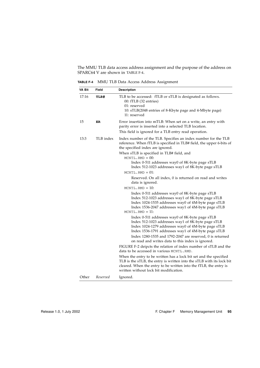
Table F-4MMU TLB Data Access Address Assignment
TLB#
MMU TLB Tag Access Register
Kbyte page entry
10.7 I/D TSB Extension Registers
10.9 I/D Synchronous Fault Status Registers I-SFSR, D-SFSR
MMU I/D Synchronous Fault Status Registers I-SFSR, D-SFSR
TSB Base Registers
Table F-5I-SFSRBit Description
EID
Table F-6describes the field encoding for ISFSR.FT
FT60 Error Description
SFSRBit Description
Isfsr Update Policy
Table F-8D-SFSRBit Description 1
Table F-8D-SFSRBit Description 2
Table F-9defines the encoding of the FT60 field
SFSRBit Description 3
Dsfsr Update Policy
MMU Synchronous Fault Status Register FT Fault Type Field
Fresh fault or miss3
Kbytes
Table F-10DSFSR Update Policy
MMU Bypass
Table F-11Bypass Attribute Bits on SPARC64
Automatic TLB Replacement Rule
TLB Replacement Policy
Restriction of sTLB Entry Direct Replacement
Page
Assembly Language Syntax
Please refer to Appendix G of Commonality
Page
Software Considerations
Please refer to Appendix H of Commonality
Page
Extending the Sparc V9 Architecture
Please refer to Appendix I of Commonality
Page
Changes from Sparc V8 to Sparc
Please refer to Appendix K of Commonality
Page
Programming with the Memory Models
Please refer to Appendix J of Commonality
Page
SPARC64 V ASI Assignments
Address Space Identifiers
SPARC64 V ASI Assignments 1
SPARC64 V ASI Assignments 2
TBD
Special Memory Access ASIs
SPARC64 V ASI Assignments 3
Block Load and Store ASIs
Partial Store ASIs
Interface Definition
Barrier Assist for Parallel Processing
High-Speed Lbsy Read Mechanism
High-Speed BST Write Mechanism
ASI Registers
Lbsy Control Register ASICLBSYR0, ASICLBSYR1
Bstw Control Register ASICBSTW0, ASICBSTW1
Bstw Busy Status Register Asicbstwbusy
EF16
Last Barrier Synchronization Status Read ASILBSYR0
Barrier State Write ASIBSTW0, ASIBSTW1
Read Write is ignored
Cache Organization
Cache Types
Table M-1L1I Cache Characteristics
Level-1 Instruction Cache L1I Cache
Level-1 Data Cache L1D Cache
Table M-2L1D Cache Characteristics
Table M-3L2 Cache Characteristics
Level-2 Unified Cache L2 Cache
Table M-4Relationships Between Cache Coherency Protocols
Cache Coherency Protocols
Cache Control/Status Instructions
Table M-5L2 Cache Moesi States
Flush Level-1 Instruction Cache
ASIFLUSHL1I
Level-2 Cache Control Register ASIL2CTRL
3 L2 Diagnostics Tag Read
Table M-6ASIL2CTRL Register Bits
4 L2 Diagnostics Tag Read Registers
ASIL2DIAGTAGREADREG
Page
Interrupt Handling
Interrupt Dispatch
Membar
Interrupt Receive
Figure N-2is an example of the interrupt receive flow
Interrupt Vector Dispatch Register
Interrupt Global Registers
Interrupt-Related ASR Registers
Interrupt Vector Dispatch Status Register
Power-on Reset POR
Reset, REDstate, and errorstate
Reset Types
Appendix contains these sections
Externally Initiated Reset XIR
Watchdog Reset WDR
Software-Initiated Reset SIR
REDstate and errorstate
Figure O-1illustrates the processor state transition diagram
PA = 000007FFF000000016
Integer registers
Processor State after Reset and in REDstate
CPU Fatal Error state
Floating Point registers
TBA6315
Mask dependent
ASI Register State After Reset and in REDstate 1
Table O-2ASR State after Reset and in REDstate
Counter
ASI Register State After Reset and in REDstate 2
Others
ASI Register State After Reset and in REDstate 3
Operating Status Register Opsr
11011 Unchanged
Firmware Initialization Sequence
Hardware Power-On Reset Sequence
To be defined later
Page
Error Classification
Error Handling
Fatal Error
Urgent Error
Errorstate Transition Error
Instruction-Obstructing Error
Urgent Error Independent of Instruction Execution
Traps for Urgent Errors
Restrainable Error
Correctable Error CE, corrected by hardware
Following registers are related to the error handling
Action and Error Control
Registers Related to Error Handling
Table P-1Registers Related to Error Handling
Table P-2summarizes what happens when an error is detected
Summary of Actions Upon Error Detection
Table P-2Action Upon Detection of an Error 1
Ideal specification
Table P-2Action Upon Detection of an Error 2
Deviation in SPARC64
Table P-2Action Upon Detection of an Error
Error Marking for Cacheable Data Error
Error Marking for Cacheable Data
Table P-3Syndrome for Data Marked for Error
Format of Error-Marking Data
Table P-4Format of Error-Marked Data
Table P-6shows the Errormarkid set by the CPU
Table P-5ERRORMARKID Bit Description
Difference Between Error Marking on SPARC64 IV
Table P-7Error Marking on SPARC64 IV and SPARC64
Table P-8 Asieidr Bit Description
Control of Error Action Asierrorcontrol
Value in ASIERRORCONTROL, as defined in Table P-9
Rteue
Weaked
Ugehandler
4C16
Fatal Error and errorstate Transition Error
Table P-10Format of Asistchgerrorinfo Bit Description
Always 0 Eeother
Types of errorstate Transition Errors
Fatal Error Types
Current SPARC64 V implementation
Ideal specification not implemented
Urgent Error
Table P-11ASIUGESR Bit Description 1
Table P-11ASIUGESR Bit Description 2
Table P-11ASIUGESR Bit Description 3
Table P-11ASIUGESR Bit Description 4
Action of asyncdataerror ADE Trap
Conditions that cause ADE trap
Instend Priv Mugedae Mugeiae Mugeiuge
Following actions are executed in this order
Set the specific register setting
Following three sets of registers are updated
State transition
Upon completion of a Retry or Done instruction
Update of ASIUGESR, as shown in Table P-13
Instruction End-Method at ADE Trap
Instend
Expected Software Handling of ADE Trap
Void ExpectedsoftwarehandlingofADEtrap
Data Access Errors
Instruction Access Errors
See Appendix F, Memory Management Unit, for details
Restrainable Errors
Asiasyncfaultstatus Asiafsr
DGL1$U2$STLB
Ceincomed
UERAWL2$INSD
Uedstbeto
UERAWL2$FILL
Implementation Deviation SPARC64 V sets
Contents
WAY
ASIASYNCFAULTADDRU2 register is described in Table P-17
Syndrome
Expected Software Handling of Restrainable Errors
Contents of PABIT423
Page
Table P-18shows error handling for most registers
Handling of Internal Register Errors
Register Error Handling Excluding ASRs and ASI Registers
Terminology used in Table P-18is defined as follows
Table P-19ASR Error Handling
ASR Error Handling
Table P-19shows the handling of ASR errors
ADE trap, W
Terminology used in Table P-20is defined as follows
ASI Register Error Handling
Error Protect
Parity Always
Error Detect Condition
Error Type
Correction
Table P-20shows the handling of ASI register errors
Table P-20Handling of ASI Register Errors
Table P-20Handling of ASI Register Errors
SPARC64 V Implementation and the Ideal Specification
Cache Error Handling
Handling of a Cache Tag Error
Error in D1 Cache Tag and I1 Cache Tag
Error in U2 Unified Level 2 Cache Tag
Handling of a D1 Cache Data Error
Handling of an I1 Cache Data Error
Correctable Error in D1 Cache Data
Marked Uncorrectable Error in D1 Cache Data
Marked Uncorrectable Error in U2 Cache Data
Handling of a U2 Cache Data Error
Correctable Error in U2 Cache Data
Raw Uncorrectable Error in U2 Cache Data
Way Reduction Condition
Automatic Way Reduction of I1 Cache, D1 Cache, and U2 Cache
I1 Cache Way Reduction
D1 Cache Way Reduction
U2 Cache Way Reduction
Error in TLB Entry Detected on Ldxa Instruction Access
TLB Error Handling
Handling of TLB Entry Errors
Table P-22Error Protection and Detection of TLB Entries
Automatic Way Reduction of sTLB
Handling of Extended UPA Data Bus Error
Handling of Extended UPA Bus Interface Error
Handling of Extended UPA Address Bus Error
STLB Way Reduction
Correctable Error on Extended UPA Data Bus
UE in Outgoing Data to Extended UPA Data Bus
Page
Sample Pseudocodes
Performance Instrumentation
Performance Monitor Overview
Counter Clear/Set
Counter Event Selection and Start
Counter Stop and Read
Performance Monitor Description
Table Q-1Events and Encoding of Performance Monitor
Instruction Statistics
Events and Encoding of Performance Monitor
Instruction Count instructioncounts
Counts the committed Floating Multiply-and-Add instructions
Trap-Related Statistics
Counts the occurrences of instruction uTLB misses
MMU Event Counters
Counts the occurrences of Tcc instructions
Counts the occurrences of data uTLB misses
Counts the occurrences of D1 cache misses
Cache Event Counters
Counts the occurrences of I1 cache misses
Counts the total latency of I1 cache misses
Counts the occurrences of L2 cache miss by demand access
Counts L2 cache references by demand read access
Counts the number of Scpireq packets received
UPA Event Counters
Counts the number of Sinvreq packets received
Counts the number of Scpbreq packets received
Miscellaneous Counters
Barrier-Assist ASI Read Count asirdbar
Page
Table R-1shows the mapping of the CPU’s UPA port slave area
UPA Programmer’s Model
Mapping of the CPU’s UPA Port Slave Area
Table R-1CPU’s UPA Port Slave Area Mapping
UPA PortID Register
Table R-2UPA PortID Register Fields
UPA PortID Register Fields
UPA Config Register
Table R-3UPA Config Register Description
Upacap
UPA Config Register Description
MID
Pcon
UPCCAP2
Upccap
Page
Summary of Differences between SPARC64 V and UltraSPARC-III
SPARC64 V and UltraSPARC-III Differences 1
Table T-1SPARC64 V and UltraSPARC-III Differences 2
UPA
Table T-1SPARC64 V and UltraSPARC-III Differences 3
Sfsr
Page
General References
Bibliography
Please refer to Bibliography in Commonality
Page
Index
Auge
Page
ASIINTRW133
Page
Error detection action155
DAE
DGL1$L2$STLB error194 DGL1$U2$STLB error195
On Jmpl instruction error53 update during MMU trap90
Dmmu
ECCerror exception46, 153, 155
Persistence38
Statistics monitoring206-207
FQ17
FSR
Immu
Update during MMU trap90
Isfsr
Lddfa instruction80
PSO41 RMO41
OBP
Release 1.0, 1 July Chapter Index
PTE
Release 1.0, 1 July Chapter Index
Page
TLB
Way reduction194 uDTLB10, 85
UITLB10, 85, 90 uncorrectable error152
UnimplementedFPop floating-point trap type70