Getting Started
The Display Layout
The Display Layout
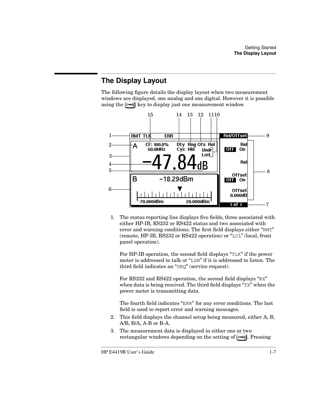
The following figure details the display layout when two measurement windows are displayed, one analog and one digital. However it is possible
using the ![]() key to display just one measurement window.
key to display just one measurement window.
15 | 14 | 13 | 12 | 1110 | ||||
1 |
|
|
|
|
|
|
| 9 |
2 |
|
|
|
|
|
|
|
|
|
|
|
|
|
|
|
| |
3 |
|
|
|
|
|
|
|
|
4 |
|
|
|
|
|
|
|
|
|
|
|
|
|
|
|
| |
5 |
|
|
|
|
|
|
| 8 |
|
|
|
|
|
|
| ||
6 |
|
|
|
|
|
|
| 7 |
|
|
|
|
|
|
| ||
|
|
|
|
|
|
|
| |
1.The status reporting line displays five fields, three associated with either
For
For RS232 and RS422 operation, the second field displays “RX” when data is being received. The third field displays “TX” when the power meter is transmitting data.
The fourth field indicates “ERR” for any error conditions. The last field is used to report error and warning messages.
2.This field displays the channel setup being measured, either A, B, A/B, B/A,
3.The measurement data is displayed in either one or two
rectangular windows depending on the setting of ![]() . Pressing
. Pressing
HP E4419B User’s Guide |
