Power Meter Operation
Setting Measurement Limits
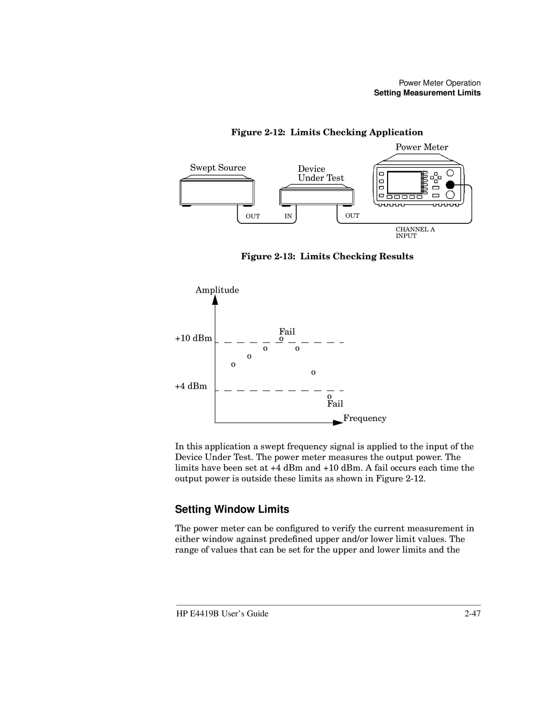
Figure 2-12: Limits Checking Application
Power Meter
Swept Source |
| Device |
|
| Under Test |
OUT | IN | OUT |
CHANNEL A
INPUT
Figure 2-13: Limits Checking Results
Amplitude |
| ||
+10 dBm | Fail | ||
o | |||
|
| o | o |
|
| o |
|
|
| o | o |
|
|
| |
+4 dBm |
| ||
o Fail
Frequency
In this application a swept frequency signal is applied to the input of the Device Under Test. The power meter measures the output power. The limits have been set at +4 dBm and +10 dBm. A fail occurs each time the output power is outside these limits as shown in Figure
Setting Window Limits
The power meter can be configured to verify the current measurement in either window against predefined upper and/or lower limit values. The range of values that can be set for the upper and lower limits and the
HP E4419B User’s Guide |