Power Meter Operation
Zeroing and Calibrating the Power Meter
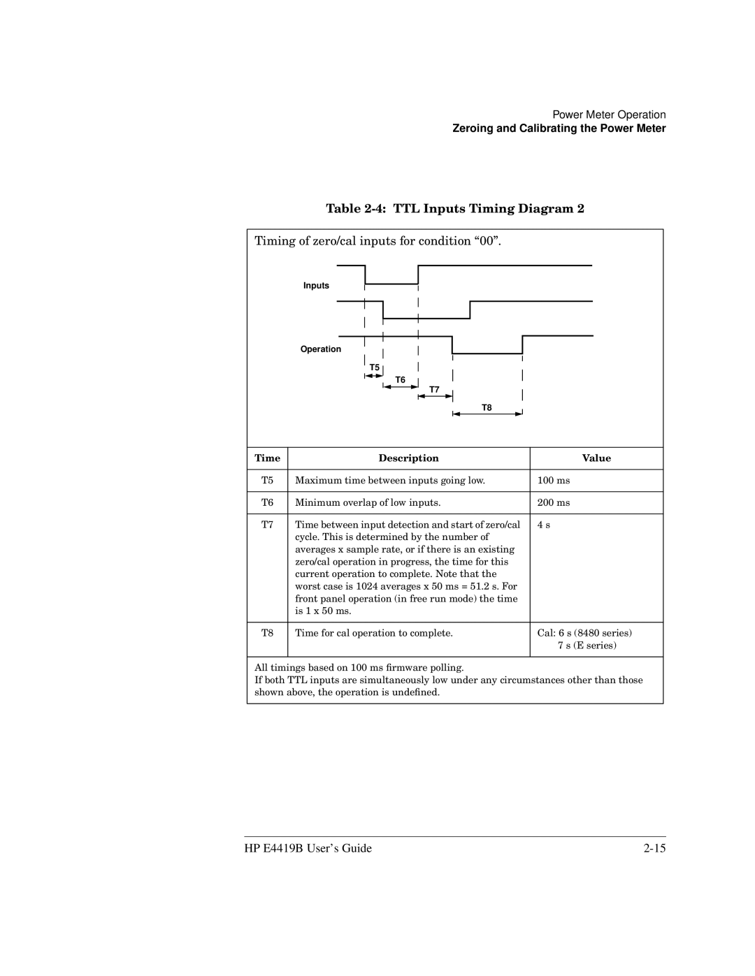
Table 2-4: TTL Inputs Timing Diagram 2
Timing of zero/cal inputs for condition “00”.
Inputs
Operation
T5
T6
T7
T8
Time | Description | Value |
|
|
|
T5 | Maximum time between inputs going low. | 100 ms |
|
|
|
T6 | Minimum overlap of low inputs. | 200 ms |
|
|
|
T7 | Time between input detection and start of zero/cal | 4 s |
| cycle. This is determined by the number of |
|
| averages x sample rate, or if there is an existing |
|
| zero/cal operation in progress, the time for this |
|
| current operation to complete. Note that the |
|
| worst case is 1024 averages x 50 ms = 51.2 s. For |
|
| front panel operation (in free run mode) the time |
|
| is 1 x 50 ms. |
|
|
|
|
T8 | Time for cal operation to complete. | Cal: 6 s (8480 series) |
|
| 7 s (E series) |
|
|
|
All timings based on 100 ms firmware polling.
If both TTL inputs are simultaneously low under any circumstances other than those shown above, the operation is undefined.
HP E4419B User’s Guide |