Power Meter Operation
Making Measurements using Sensor Calibration Tables
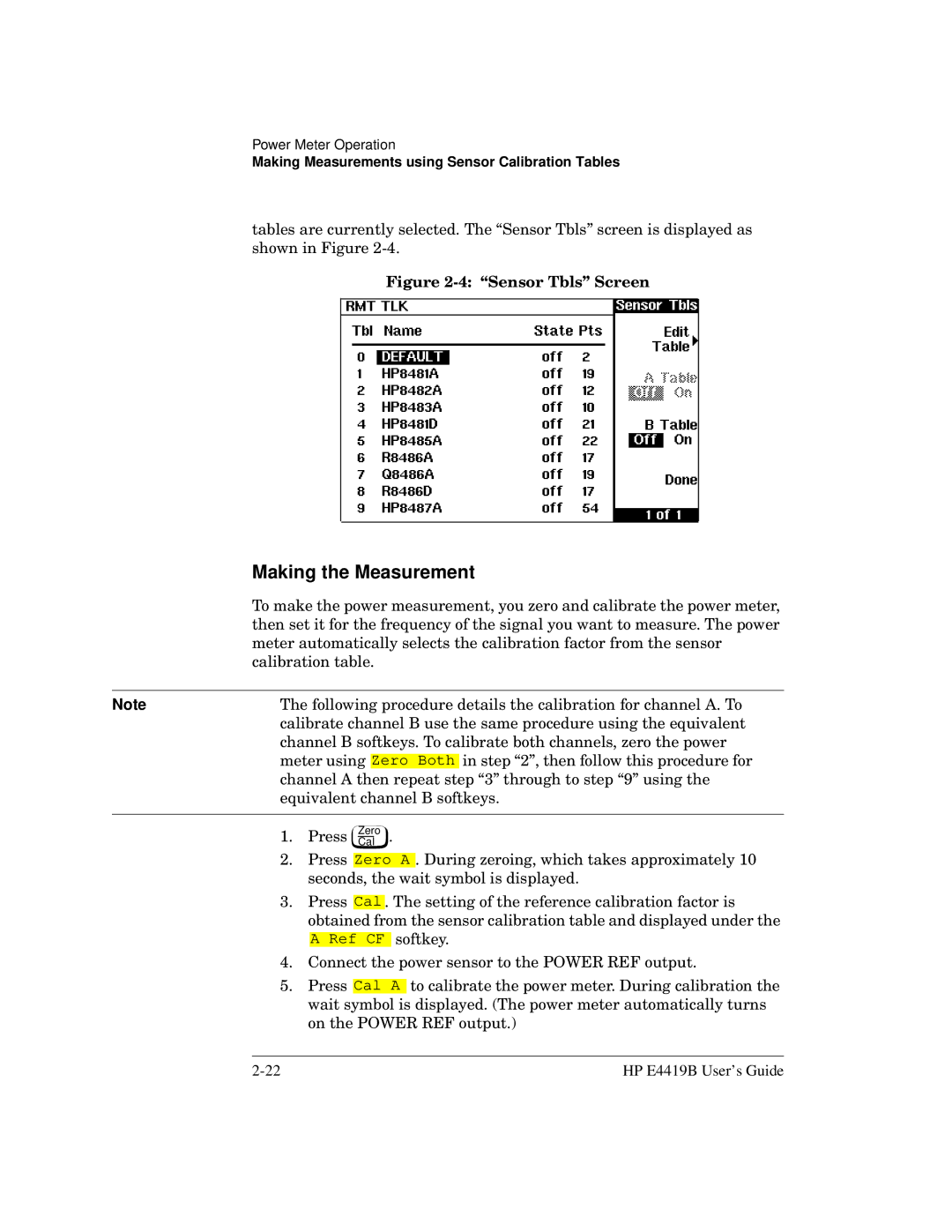
tables are currently selected. The “Sensor Tbls” screen is displayed as shown in Figure
Figure 2-4: “Sensor Tbls” Screen
| Making the Measurement | ||||||||||||
| To make the power measurement, you zero and calibrate the power meter, | ||||||||||||
| then set it for the frequency of the signal you want to measure. The power | ||||||||||||
| meter automatically selects the calibration factor from the sensor | ||||||||||||
| calibration table. | ||||||||||||
|
|
|
|
|
|
|
|
|
|
|
|
| |
Note | The following procedure details the calibration for channel A. To | ||||||||||||
| calibrate channel B use the same procedure using the equivalent | ||||||||||||
| channel B softkeys. To calibrate both channels, zero the power | ||||||||||||
| meter using |
|
|
|
|
|
| in step “2”, then follow this procedure for | |||||
| Zero Both | ||||||||||||
| channel A then repeat step “3” through to step “9” using the | ||||||||||||
| equivalent channel B softkeys. | ||||||||||||
|
|
|
|
|
|
|
|
|
|
|
|
|
|
| 1. | Press |
| . |
|
| |||||||
| Zero | ||||||||||||
| Cal | ||||||||||||
| 2. | Press |
|
|
|
| . During zeroing, which takes approximately 10 | ||||||
| Zero A | ||||||||||||
|
| seconds, the wait symbol is displayed. | |||||||||||
| 3. | Press |
| . The setting of the reference calibration factor is | |||||||||
| Cal | ||||||||||||
|
| obtained from the sensor calibration table and displayed under the | |||||||||||
|
|
|
|
|
| softkey. | |||||||
|
|
| A Ref CF | ||||||||||
| 4. | Connect the power sensor to the POWER REF output. | |||||||||||
| 5. | Press |
|
| to calibrate the power meter. During calibration the | ||||||||
|
| Cal A | |||||||||||
|
| wait symbol is displayed. (The power meter automatically turns | |||||||||||
|
| on the POWER REF output.) | |||||||||||
HP E4419B User’s Guide |