Getting Started
The Rear Panel at a Glance
The Rear Panel at a Glance
1 | 2 | 3 | 4 | 5 | |||||||||
|
|
|
|
|
|
|
|
|
|
|
|
|
|
|
|
|
|
|
|
|
|
|
|
|
|
|
|
|
|
|
|
|
|
|
|
|
|
|
|
|
|
|
|
|
|
|
|
|
|
|
|
|
|
|
|
|
|
|
|
|
|
|
|
|
|
|
|
|
|
|
|
|
|
|
|
|
|
|
|
|
|
|
|
|
|
|
|
|
|
|
|
|
|
|
|
|
|
|
|
|
|
|
|
|
|
|
|
|
|
|
|
|
|
|
|
|
|
|
|
|
|
|
|
|
|
10 | 9 | 8 | 7 | 11 | 6 |
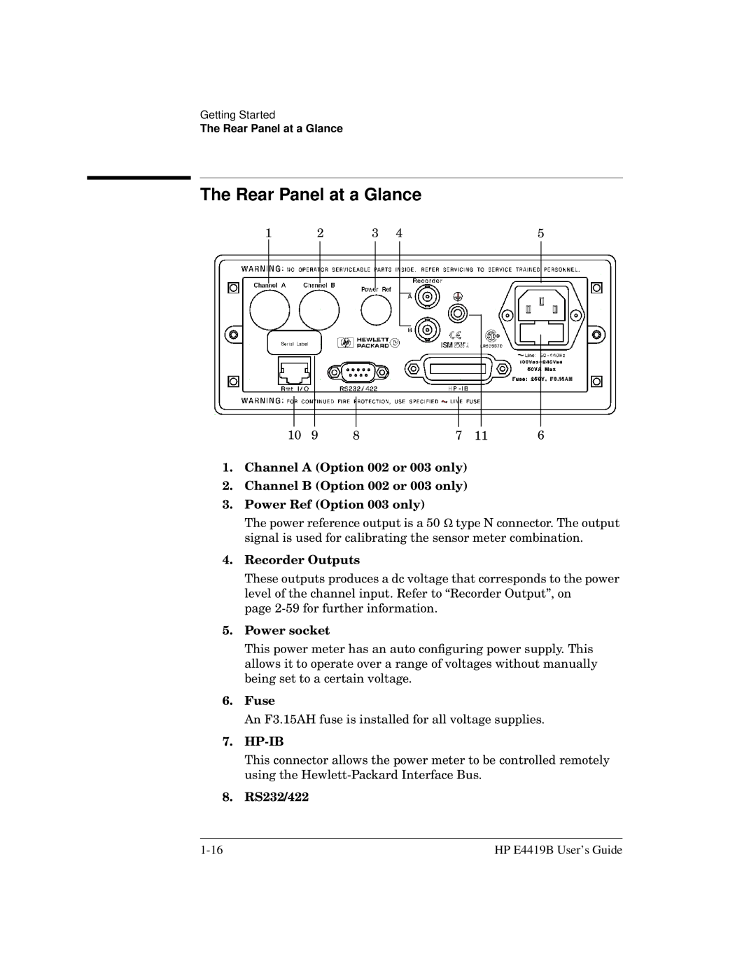
1.Channel A (Option 002 or 003 only)
2.Channel B (Option 002 or 003 only)
3.Power Ref (Option 003 only)
The power reference output is a 50 Ω type N connector. The output signal is used for calibrating the sensor meter combination.
4.Recorder Outputs
These outputs produces a dc voltage that corresponds to the power level of the channel input. Refer to “Recorder Output”, on
page
5.Power socket
This power meter has an auto configuring power supply. This allows it to operate over a range of voltages without manually being set to a certain voltage.
6.Fuse
An F3.15AH fuse is installed for all voltage supplies.
7.HP-IB
This connector allows the power meter to be controlled remotely using the
8.RS232/422
HP E4419B User’s Guide |