FaxFinder
Patents
Warranty
S000405E, Version E
Copyright 2009, by Multi-Tech Systems, Inc
Contents
Product Description
Product Description Specifications
Prerequisite Determining PBX Compatibility & Configuration
Ethernet Ports Caution
Safety Warnings
Lithium Battery Caution
Telecom
Technical Specifications
Related Manuals
Distributing Documents to Client Users
Title Format Purpose
You Supply
Introduction
PBX Compatibility
We Supply
Mechanical Mounting
Quick Hookup
FF120/220
FF420/820
FF-420/820 Unit
Earth Grounding for FF420/820
FaxFinder Operating Modes
FaxFinder Operating Modes
Connect FaxFinder to AC Outlet
FF-120/220
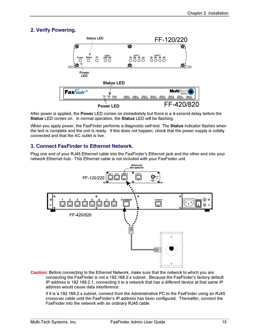
Status LED
Verify Powering
Power LED
Connect FaxFinder to Ethernet Network
Connection for Automated Routing Mode
Part B Connecting to Telephony Service
Installing the Device Manager software
Part C Installing the Software
Page
Page
Installing the Client software
Page
Page
Page
Client Install on Terminal Service
Push Installs of the Client Software
Older must be uninstalled before upgrading
FaxFinder Client Install Shield Mass Uninstall
FaxFinder Client Terminal Services MSI Installer
Summary of Configuration Data
Part D Configuring the FaxFinder Server
Manual Routing Mode Mapping of FF Ports to Phone Numbers
Windows XP/2003
Setting Admin PC to Startup IP Address
Page
Either type http//192.168.2.1 and press Enter
Logging
Resetting Admin PC to Its Regular IP Address
Setting FaxFinder IP Addresses
Setting Administrative Functions
Log In After Reset
B1. Pots Line n Rows Automated Routing Mode only
B1. Pots Line n Rows Manual Routing Mode only
B2. Pots Line n Rows Finishing
Personal Email Address for Administrator optional
Configuring the FaxFinder’s Modems
Setting up the Mail Server
Page
Page
Specifying Administrator’s Client Password
Changing Administrator Server Password
Sending Test Fax from Fax Machine to FaxFinder
Page
Adding Client-Users to the Phone Book
Home Screen
FaxFinder Server Software Screens
Login Screen
Fax Log Screen
Command Buttons Description
Fax Details Screen Field Definitions Values Description
Fax Details Screen
Multi-Tech Systems, Inc FaxFinder Admin User Guide
Current Status Screen
Current Status Screen Field Definitions cont’d Field Name
Description System fields Group
Pots Modem n Fields group
Logout Option
Administration Screen
Fields
Administration Screen Field Definitions
Smtp Configuration Fields
Field Name Values Description
Smtp Configuration Fields
Reset Unit fields
Phone Book Screen
Automated Routing Mode where the Routing field
Model-specific mode codes are as follows
Modem Configuration Screen
Routing Definition
Identification Fax Header Local ID
FaxFinder Send Fax screen
Modem Configuration Table
Password Administration Screen
Shared Resources Screen
Establishing Client User’s ID in System
FaxFinder Client Software Configuration
Associating Client with Specific FaxFinder Units
Page
Disassociating the Client from a Specific FaxFinder Unit
Sending Test Fax
Disabling and Re-Enabling a Client’s FaxFinder Service
FaxFinder Fax Client Software Menu Command Definitions
Enter a Fax Recipient window, that
FaxFinder Send Fax Screen
Documents Pane
FaxFinder Send Fax Screen Definitions cont’d
Values Description Recipients pane
Address Book. If you check the Remember this
FaxFinder Client Software Configuration
Multi-Tech Systems, Inc FaxFinder Admin User Guide
Guides for detailed instructions. An About
Help menu commands
Descriptor
FaxFinder Client Software Configuration
Descriptor
Ddd mmm nn Hhmmss zzzzzz
Shows the organizational affiliation
Export
Import
FaxFinder Client Software Operation
Sending a Fax
Page
Multi-Tech Systems, Inc FaxFinder Admin User Guide
Page
Page
Page
Scheduling Fax Transmissions
Re-Sending a Failed Fax
Putting Pending Faxes on Hold and Removing the Hold
Page
Page
Canceling a Fax
Setting Fax Retry Number and Interval
Sending One Fax Containing Multiple Documents
Page
Forwarding a Fax
Receiving a Fax
Receiving Faxes in Manual Routing Mode
Page
Receiving Faxes in Automated Routing Mode
Frequently Used Commands Toolbar Icons
Using the Multi-Tech Tiff Viewer
Page
Page
Page
Page
Importing Fax Images into Other Application Programs
Setting up Your Address Book Manually
Page
Page
Setting up Your Address Book by Synchronizing with Outlook
Synchronization Procedure
What Synchronization Means
Page
Page
Setting Up Address Books with CSV Files
Page
Exporting a FaxFinder Address Book to CSV File Format
FaxFinder Client Software Operation
Page
Page
FaxFinder Client Software Operation
Page
Page
Page
Page
Page
FaxFinder Client Software Operation
Page
Cover Pages
Using Stock Cover Pages
Page
Page
Page
Page
Creating New Cover Page Templates
Creating or Modifying Cover Page Styles
Page
FF Client Add Device Address
Page
Not supported
Shape Cursors
Page
Modifying Existing Cover Page Templates
Page
Page
Page
Page
Page
File Menu
Cover Page Generator Menu/Icon Command Descriptions
Insert Menu
Edit Menu
Deleting objects
View Menu
Settings Menu
Reporting Failed Faxes to the Administrator
Fax Log Email Messages
Server Operation
Or LAN1 LEDs
Line 1/2 LEDs on FF-120/220 Modem 1-4 or On FF-420/820
Possible Solutions to Fax Failure Problems
Dealing with Failed Fax Reports
Failure Analysis Factors to Consider
Opening the Device Manager Software
Device Manager Operation
Device Manager Main Screen
Right-Click on listed device
Access to Commands
How to Access Command Command Name Summary
Right-Click ‘Device’ Menu
Main Screen Menu or Column Description
Device Manager File Menu
File Menu Command Description of Fields & Buttons
Device Manager Edit Menu
Edit Menu Command Description
Synchronizing Phonebooks
Page
Adding Devices
Using the Auto-Discovery Monitor
Page
Deleting a Device
Saving a Configuration
Restoring a Configuration
Exporting a CSV Phonebook
Page
Importing a CSV Phonebook
Page
Page
Page
Page
Page
Page
Retrieving Received Faxes
Setting Phone Book Sharing
Firmware Updating Process
Modem Firmware Update
Currently installed
Click Start Update
Page
Server Firmware Update
Click Start Update
Page
Page
What if I cant see the web page for my FaxFinder?
Appendix a Troubleshooting
Page
My FaxFinder 120 or 220 is no longer responding to my inputs
Remedy for Manual Routing Mode
Remedy for Automated Routing Mode
What if the FaxFinder doesnt answer a fax call?
Error Message Explanation
Smtp Error Code List
CFR Part 68 Telecom
Appendix B Regulatory Information
MT5634SMI
CFR Part 15 Regulation
Fax Branding Statement
Canadian Limitations Notice
Industry Canada
Waste Electrical and Electronic Equipment
Weee Statement
Rohs HT/TS Substance Concentration
依照中国标准的有毒有害物质信息
Sample FaxFinder Systems
Appendix C Example Systems
Automated Routing Mode Manual Routing Mode
FaxFinder Server Software Setup
Server Setup for Sample FaxFinder System
Receiving a Fax, Server Perspective
Pstn
Receiving a Fax, Client Perspective
Time Name
Sending a Fax, Server Perspective
Sample Client Setup
Address Book Methods of Management
Page
Page
Printing to FaxFinder What Administrators Must Tell Users
Sending a Fax, Client Perspective
Fax Message Components
How the FaxFinder’s outgoing fax Comes together