General Description
time or several times over a short period of time when they are powered up. If the Switch was not operable at that time, it would miss this login attempt and the attached node may give up trying and require rebooting after the Switch becomes operable.
Port Activity LED (Yellow)
Each port has its own Port Activity LED. The Port Activity LED for a particular port is ON when Class 1, 2, or 3 frames are entering or leaving the port. The Switch turns the LED ON for 50 msec. for each frame, so you should be able to see it for one frame. This LED will not light for frames following an arbitrated loop in bypass mode.
Chassis Back
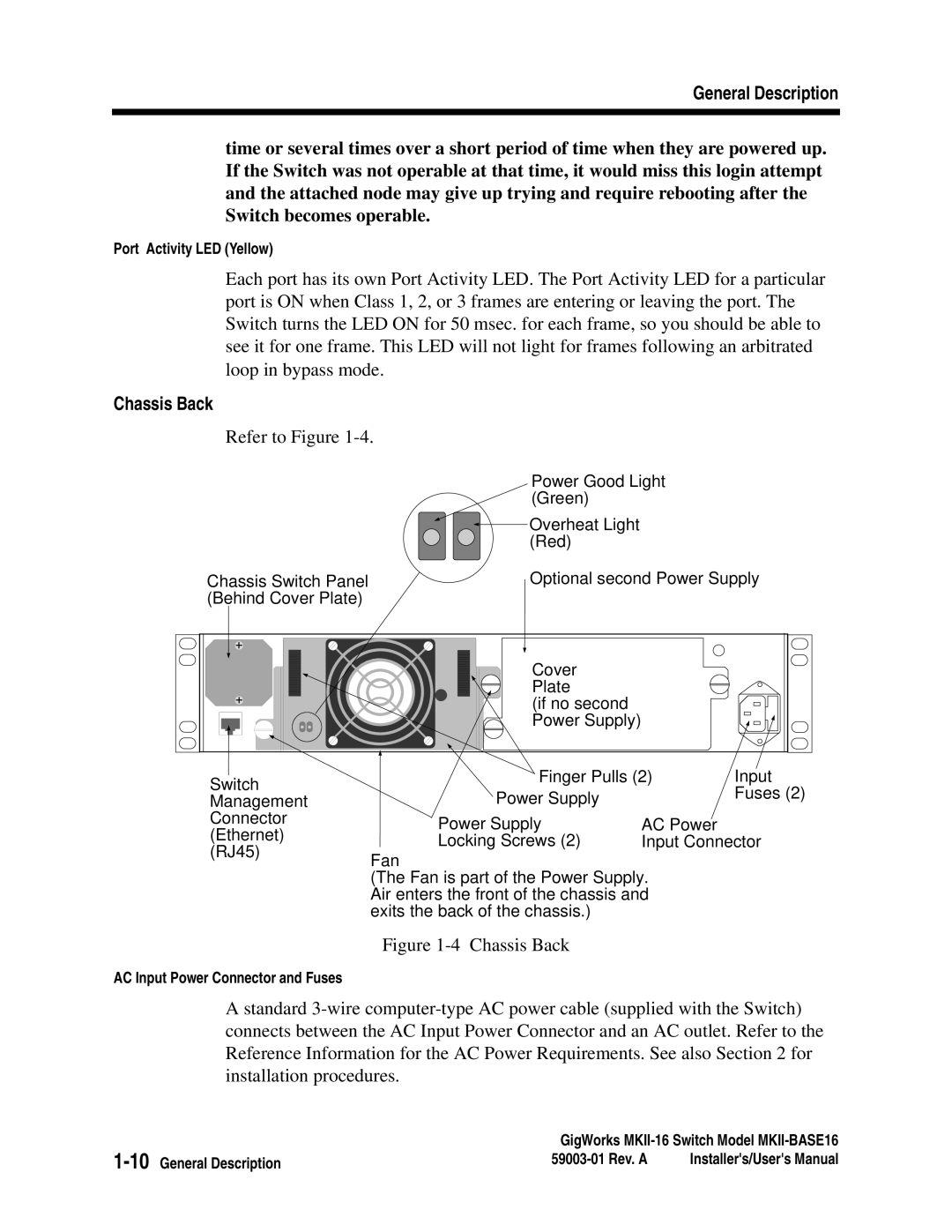
Refer to Figure 1-4.
Chassis Switch Panel
(Behind Cover Plate)
Power Good Light (Green)
![]() Overheat Light (Red)
Overheat Light (Red)
Optional second Power Supply
Cover
Plate
(if no second Power Supply)
Switch Management Connector (Ethernet) (RJ45)
Finger Pulls (2) | Input | |
Power Supply |
| Fuses (2) |
|
| |
Power Supply | AC Power |
|
Locking Screws (2) | Input Connector | |
Fan
(The Fan is part of the Power Supply. Air enters the front of the chassis and exits the back of the chassis.)
Figure 1-4 Chassis Back
AC Input Power Connector and Fuses
A standard
GigWorks | ||
Installer's/User's Manual | ||