Ethernet Cabling
Ethernet Cabling
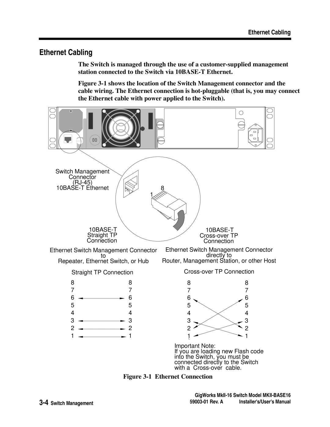
The Switch is managed through the use of a
Figure 3-1 shows the location of the Switch Management connector and the cable wiring. The Ethernet connection is hot-pluggable (that is, you may connect the Ethernet cable with power applied to the Switch).
Switch Management |
|
Connector |
|
| |
8 | |
| 1 |
|
|
| ||||
| Straight TP |
| ||||
| Connection |
| Connection | |||
Ethernet Switch Management Connector | Ethernet Switch Management Connector | |||||
| to |
| directly to | |||
Repeater, Ethernet Switch, or Hub | Router, Management Station, or other Host | |||||
Straight TP Connection | ||||||
8 | 8 | 8 | 8 | |||
7 | 7 | 7 | 7 | |||
6 |
| 6 | 6 | 6 | ||
| ||||||
5 | 5 | 5 | 5 | |||
4 | 4 | 4 | 4 | |||
3 |
|
| 3 | 3 | 3 | |
|
| |||||
2 |
|
| 2 | 2 | 2 | |
|
| |||||
1 |
|
| 1 | 1 | 1 | |
|
| |||||
Important Note:
If you are loading new Flash code into the Switch, you must be connected directly to the Switch with a
Figure 3-1 Ethernet Connection
GigWorks | ||
Installer's/User's Manual | ||