Q-Logic MKII-BASE16 user manual Cabinet Mounting Bracket

Models: MKII-BASE16

1 138
Download 138 pages 23.54 Kb
Page 31
Image 31

Installation

Philips-head screws, one in each hole in the Side Fillers.

c.Mount the Brackets. Refer to Figure 2-2. The Switch is shipped with a package containing cabinet mounting brackets and screws. You may mount these brackets on the front corners of the chassis or the back corners depending on whether you want the Switch facing the back or front of the cabinet.

Note:

If you mount the Switch in a 19” EIA rack, it must be installed on rails or on a shelf.

d.Place the Switch in a 19” EIA rack and secure it with four (4) 10-32 machine screws (not supplied). The Switch must be supported in the rack on rails or a shelf. If the Switch is supported by a shelf and the vertical space is sufficient, you may leave the rubber feet on the Switch chassis. If the vertical space is not sufficient, you may remove the rubber feet by turning them counterclockwise by hand (or with a flat-blade screwdriver). Be careful not to obstruct the airflow through the chassis (Allow 165mm (6.5”) front and back.

e.Replace the Face-plate if possible. If the Switch is facing the front of the rack the face-plate should fit. Replace the face-plate by aligning its mounting studs with the appropriate holes in the chassis front and push it straight back.

Do not obstruct the airflow through the chassis. The airflow enters the front of the chassis and exits the back.

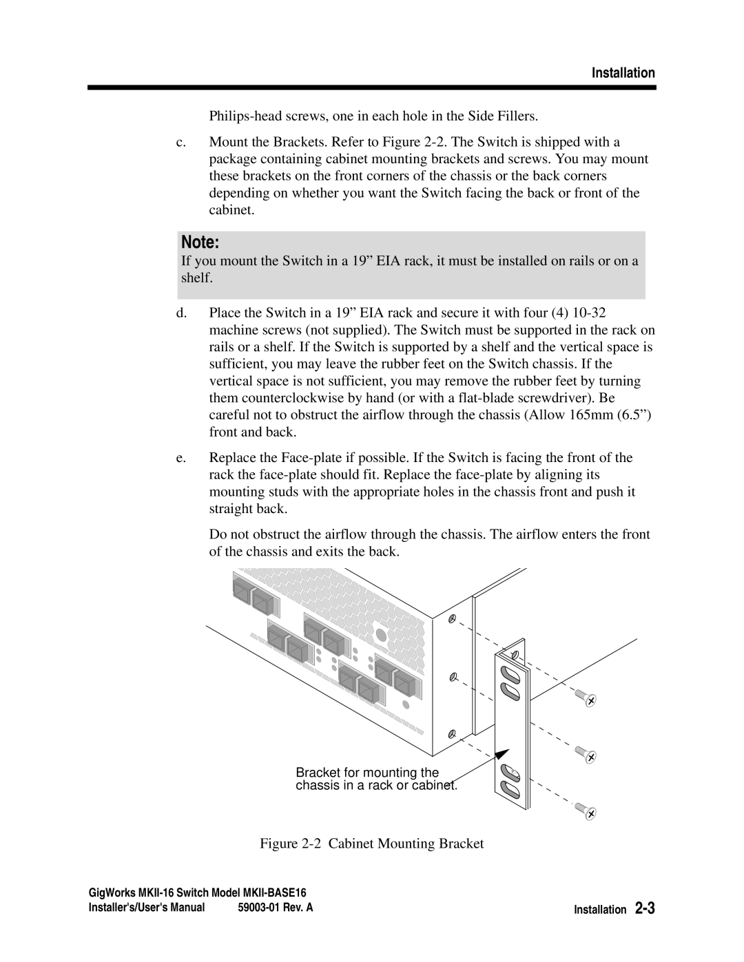
Bracket for mounting the chassis in a rack or cabinet.

Figure 2-2 Cabinet Mounting Bracket

GigWorks MKII-16 Switch Model MKII-BASE16

Installation 2-3

Installer's/User's Manual

59003-01 Rev. A

Page 31
Image 31
Q-Logic MKII-BASE16 user manual Cabinet Mounting Bracket