General Description
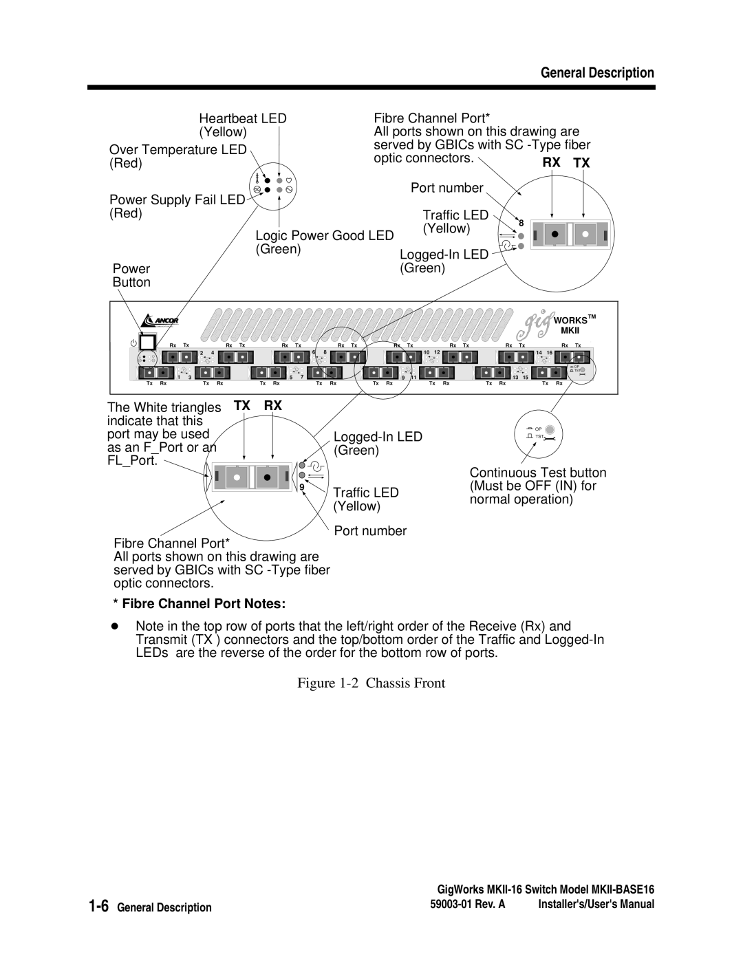
Heartbeat LED | Fibre Channel Port* |
| ||
(Yellow) | All ports shown on this drawing are | |||
Over Temperature LED | served by GBICs with SC | |||
optic connectors. | RX TX | |||
(Red) | ||||
|
| |||
Power Supply Fail LED |
| Port number |
| |
|
|
| ||
(Red) |
| Traffic LED | 8 | |
Logic Power Good LED | (Yellow) | |||
| ||||
|
| |||
(Green) |
|
| ||
|
|
| ||
Power |
| (Green) |
| |
Button |
|
|
| |
COMMUNICATIONS, INC. |
Rx![]() Tx
Tx![]()
![]()
![]()
![]()
![]() 2 4
2 4
1 3
Rx Tx![]() Rx
Rx![]() Tx
Tx![]()
![]()
![]() Rx Tx
Rx Tx ![]()
![]()
![]() Rx Tx
Rx Tx
| 6 | 8 |
|
5 | 7 | 9 | 11 |
10 12
WORKS™ |
MKII |
Rx Tx | Rx | Tx | Rx Tx |
|
| 14 | 16 |
|
|
| OP |
|
|
| TST |
| 13 | 15 |
|
Tx Rx | Tx Rx | Tx Rx | Tx Rx | Tx Rx | Tx Rx | Tx Rx | Tx Rx |
The White triangles TX RX indicate that this
port may be used as an F_Port or an FL_Port. ![]()
9![]()
Fibre Channel Port*
All ports shown on this drawing are served by GBICs with SC
Traffic LED (Yellow)
Port number
![]() OP
OP
![]() TST
TST
Continuous Test button (Must be OFF (IN) for normal operation)
* Fibre Channel Port Notes:
Note in the top row of ports that the left/right order of the Receive (Rx) and Transmit (TX ) connectors and the top/bottom order of the Traffic and
Figure 1-2 Chassis Front
GigWorks | ||
Installer's/User's Manual | ||