Appendix A Connector Wiring | Installation and Operation Manual | |
|
|
|
|
|
|
|
|
|
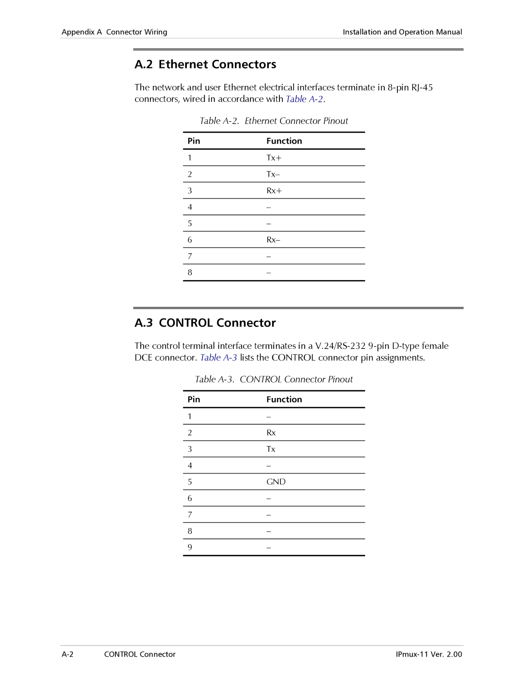
A.2 Ethernet Connectors
The network and user Ethernet electrical interfaces terminate in
Table A-2. Ethernet Connector Pinout
Pin | Function |
|
|
1 | Tx+ |
|
|
2 | Tx– |
|
|
3 | Rx+ |
|
|
4 | – |
|
|
5 | – |
|
|
6 | Rx– |
|
|
7 | – |
|
|
8 | – |
|
|
A.3 CONTROL Connector
The control terminal interface terminates in a
Table A-3. CONTROL Connector Pinout
Pin | Function |
|
|
1 | – |
|
|
2 | Rx |
|
|
3 | Tx |
|
|
4 | – |
|
|
5 | GND |
|
|
6 | – |
|
|
7 | – |
|
|
8 | – |
|
|
9 | – |
|
|
CONTROL Connector |