Chapter 2 Installation and Setup | Installation and Operation Manual | |
|
|
|
|
|
|
|
|
|
2.6 Connecting to the External Clock Source
CONTROL
EXT CLK | 1 | ETH | 3 | E1 |
2 | ||||
| SET |
|
|
|
| DEF |
|
|
|
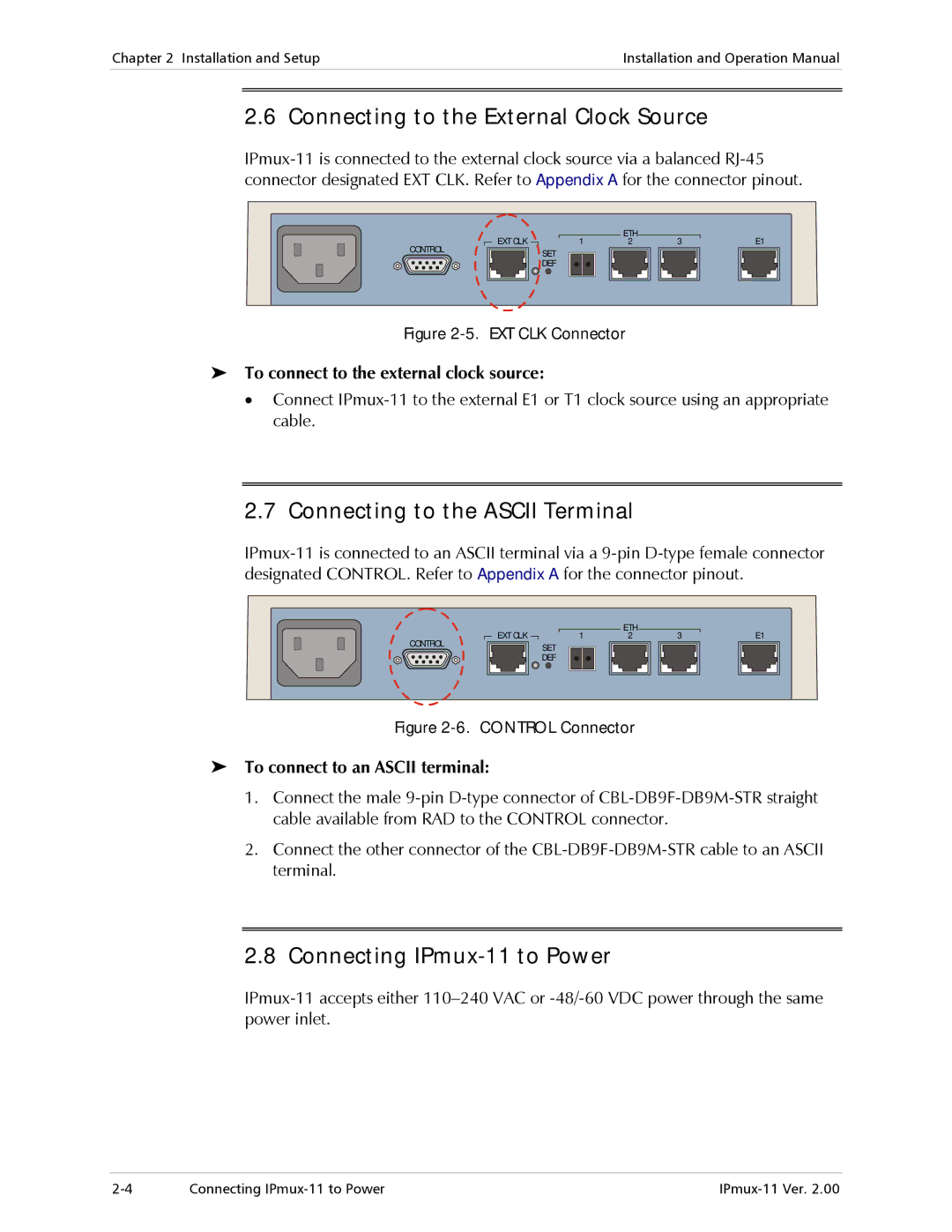
Figure 2-5. EXT CLK Connector
To connect to the external clock source:
•Connect
2.7 Connecting to the ASCII Terminal
CONTROL
EXT CLK | 1 | ETH | 3 | E1 |
2 | ||||
| SET |
|
|
|
| DEF |
|
|
|
Figure 2-6. CONTROL Connector
To connect to an ASCII terminal:
1.Connect the male
2.Connect the other connector of the
2.8 Connecting IPmux-11 to Power
Connecting |