Installation and Operation Manual | Chapter 1 Introduction | |
|
|
|
|
|
|
|
|
|
1.2 Physical Description
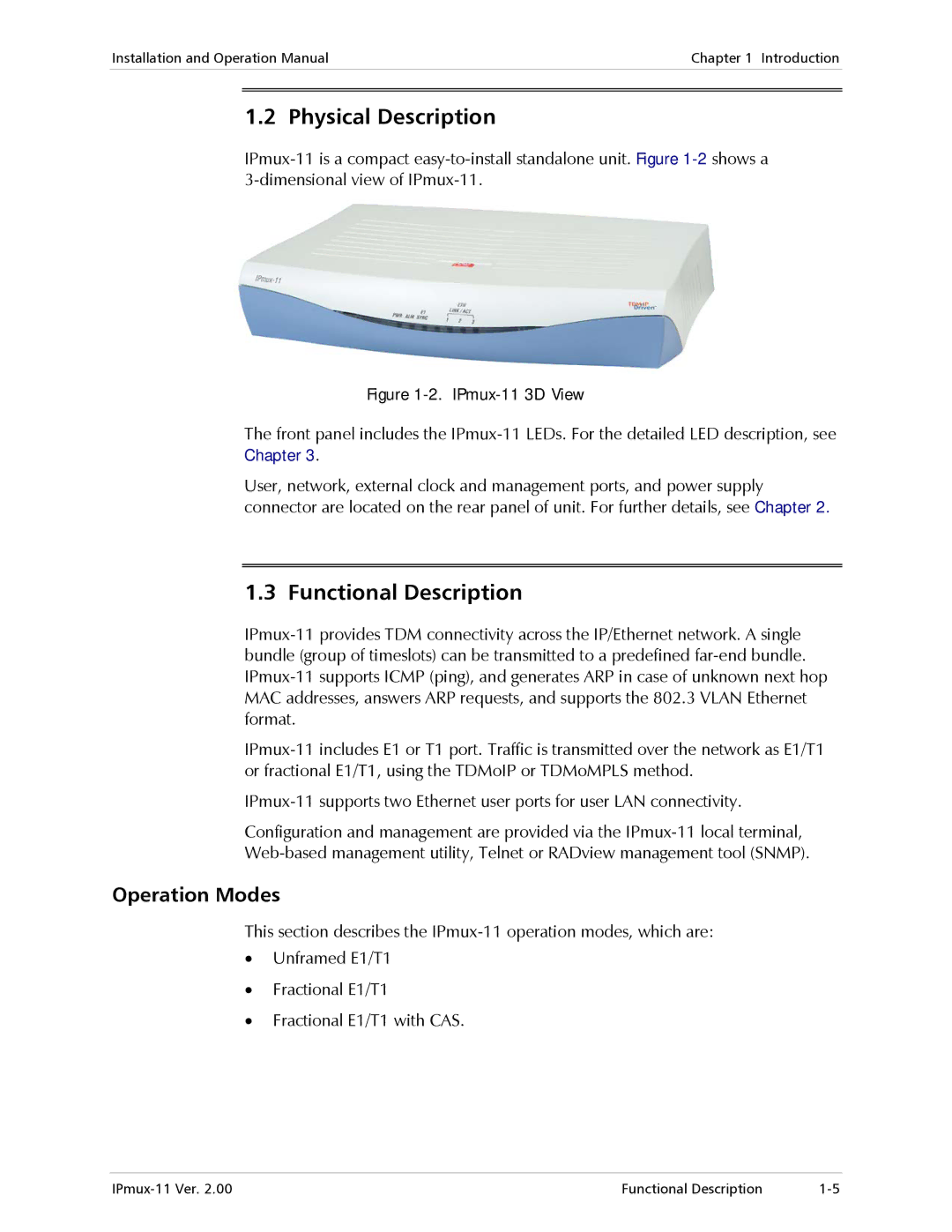
Figure 1-2. IPmux-11 3D View
The front panel includes the
User, network, external clock and management ports, and power supply connector are located on the rear panel of unit. For further details, see Chapter 2.
1.3 Functional Description
Configuration and management are provided via the
Operation Modes
This section describes the
•Unframed E1/T1
•Fractional E1/T1
•Fractional E1/T1 with CAS.
Functional Description |