Installation and Operation Manual | Chapter 2 Installation and Setup |
|
|
Connecting the Ethernet User Equipment
Figure 2-3 illustrates a rear panel of the IPmux-11 unit with two user LAN ports.
CONTROL
EXT CLK | 1 | ETH | 3 | E1 |
2 |
SET
DEF
Figure 2-3. ETH 2 and ETH 3 Connectors
To connect to the Ethernet user equipment:
•Connect
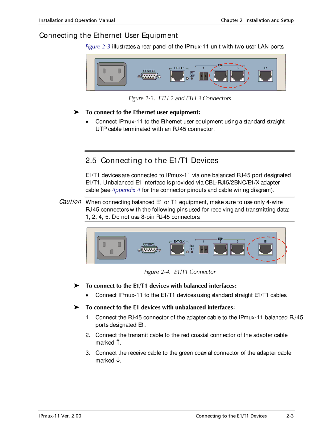
2.5 Connecting to the E1/T1 Devices
E1/T1 devices are connected to
Caution When connecting balanced E1 or T1 equipment, make sure to use only
| EXT CLK | 1 | ETH | 3 | E1 |
CONTROL | 2 | ||||
| SET |
|
|
| |
|
|
|
|
| |
|
| DEF |
|
|
|
Figure | E1/T1 Connector |
|
|
| |
To connect to the E1/T1 devices with balanced interfaces:
•Connect
To connect to the E1 devices with unbalanced interfaces:
1.Connect the
2.Connect the transmit cable to the red coaxial connector of the adapter cable marked ↑.
3.Connect the receive cable to the green coaxial connector of the adapter cable marked ↓.
Connecting to the E1/T1 Devices |