Installation and Operation ManualChapter 6 Troubleshooting and Diagnostics
| Table |
|
|
Alarm | Description |
|
|
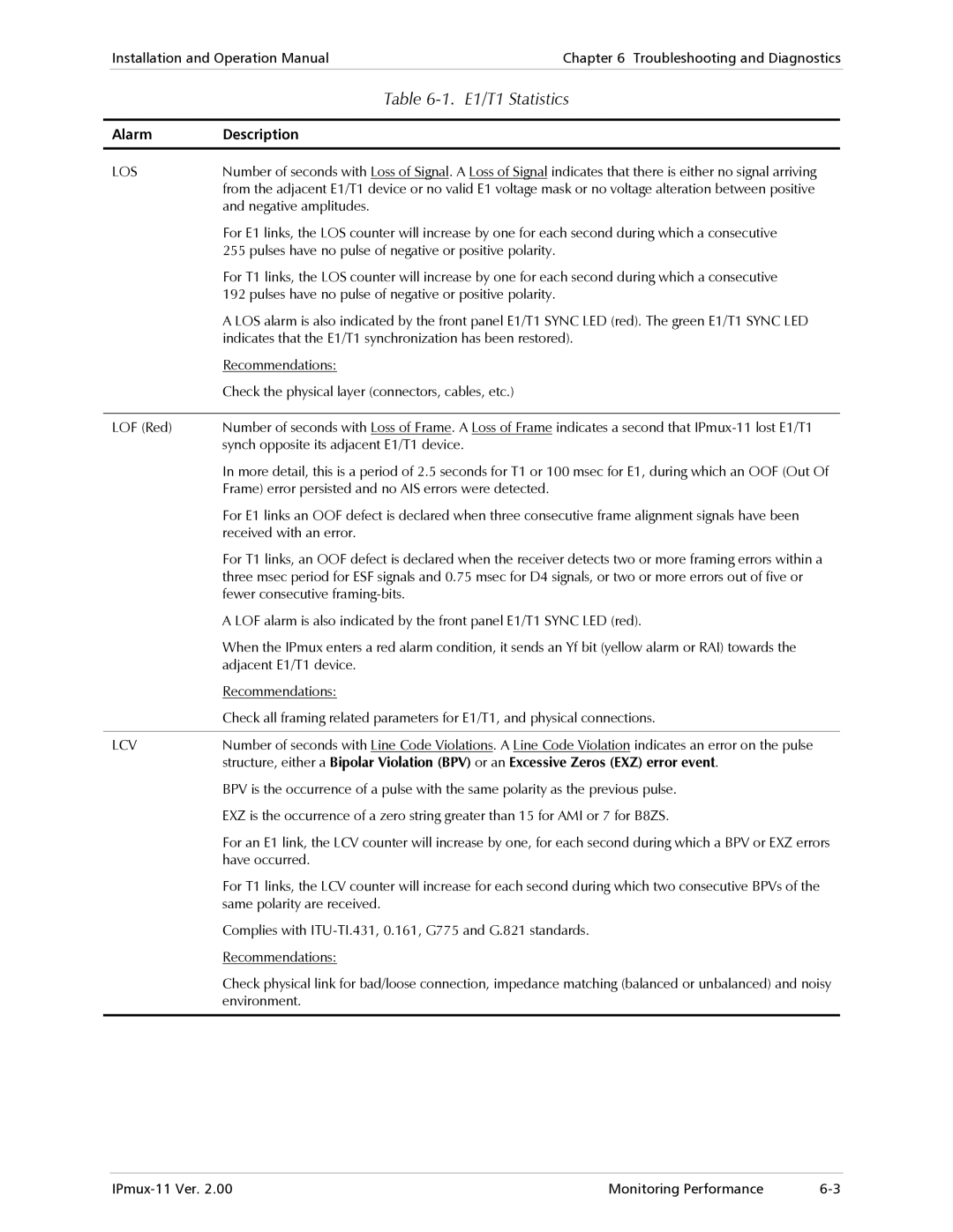
LOS | Number of seconds with Loss of Signal. A Loss of Signal indicates that there is either no signal arriving |
| from the adjacent E1/T1 device or no valid E1 voltage mask or no voltage alteration between positive |
| and negative amplitudes. |
| For E1 links, the LOS counter will increase by one for each second during which a consecutive |
| 255 pulses have no pulse of negative or positive polarity. |
| For T1 links, the LOS counter will increase by one for each second during which a consecutive |
| 192 pulses have no pulse of negative or positive polarity. |
| A LOS alarm is also indicated by the front panel E1/T1 SYNC LED (red). The green E1/T1 SYNC LED |
| indicates that the E1/T1 synchronization has been restored). |
| Recommendations: |
| Check the physical layer (connectors, cables, etc.) |
|
|
LOF (Red) | Number of seconds with Loss of Frame. A Loss of Frame indicates a second that |
| synch opposite its adjacent E1/T1 device. |
| In more detail, this is a period of 2.5 seconds for T1 or 100 msec for E1, during which an OOF (Out Of |
| Frame) error persisted and no AIS errors were detected. |
| For E1 links an OOF defect is declared when three consecutive frame alignment signals have been |
| received with an error. |
| For T1 links, an OOF defect is declared when the receiver detects two or more framing errors within a |
| three msec period for ESF signals and 0.75 msec for D4 signals, or two or more errors out of five or |
| fewer consecutive |
| A LOF alarm is also indicated by the front panel E1/T1 SYNC LED (red). |
| When the IPmux enters a red alarm condition, it sends an Yf bit (yellow alarm or RAI) towards the |
| adjacent E1/T1 device. |
| Recommendations: |
| Check all framing related parameters for E1/T1, and physical connections. |
|
|
LCV | Number of seconds with Line Code Violations. A Line Code Violation indicates an error on the pulse |
| structure, either a Bipolar Violation (BPV) or an Excessive Zeros (EXZ) error event. |
| BPV is the occurrence of a pulse with the same polarity as the previous pulse. |
| EXZ is the occurrence of a zero string greater than 15 for AMI or 7 for B8ZS. |
| For an E1 link, the LCV counter will increase by one, for each second during which a BPV or EXZ errors |
| have occurred. |
| For T1 links, the LCV counter will increase for each second during which two consecutive BPVs of the |
| same polarity are received. |
| Complies with |
| Recommendations: |
| Check physical link for bad/loose connection, impedance matching (balanced or unbalanced) and noisy |
| environment. |
|
|
Monitoring Performance |