Installation and Operation Manual | Chapter 4 Configuration |
|
|
Configuration Example
Local Management
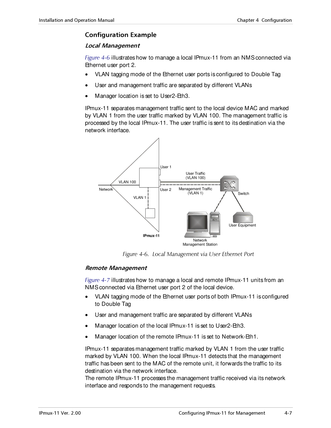
Figure 4-6 illustrates how to manage a local IPmux-11 from an NMS connected via Ethernet user port 2.
•VLAN tagging mode of the Ethernet user ports is configured to Double Tag
•User and management traffic are separated by different VLANs
•Manager location is set to User2-Eth3.
IPmux-11 separates management traffic sent to the local device MAC and marked by VLAN 1 from the user traffic marked by VLAN 100. The management traffic is processed by the local IPmux-11. The user traffic is sent to its destination via the network interface.
|
|
|
|
|
|
|
| User 1 |
|
| User Traffic |
|
| ||||||
|
|
|
|
|
|
|
|
|
|
|
|
|
|
| |||||
| VLAN 100 |
|
|
|
|
|
|
|
|
|
|
| (VLAN 100) |
|
| ||||
|
|
|
|
|
|
|
|
|
|
|
|
|
|
|
|
| |||
Network |
|
|
|
|
|
|
|
|
|
| Management Traffic |
|
| ||||||
|
|
|
|
|
|
| User 2 |
|
|
| |||||||||
|
|
|
|
|
| ||||||||||||||
| VLAN 1 |
|
|
|
|
|
|
|
|
|
| (VLAN 1) |
|
| |||||
|
|
|
|
|
|
|
|
|
| ||||||||||
|
|
|
|
|
|
|
|
|
|
|
|
|
|
|
|
| |||
|
|
|
|
|
|
|
|
|
|
| |||||||||
|
|
|
|
|
|
|
|
|
|
|
|
|
|
|
|
|
|
|
|
|
|
|
|
|
|
|
|
|
|
|
|
|
|
|
|
|
|
|
|
|
|
|
|
|
|
|
|
|
|
|
|
|
|
|
|
|
|
|
|
|
|
|
|
|
|
|
|
|
|
|
|
|
|
|
|
|
|
|
|
|
|
|
|
|
|
|
|
|
|
|
|
|
|
|
|
|
|
|
|
|
|
|
|
|
|
|
|
|
|
|
|
|
|
|
|
|
|
|
|
|
|
|
|
|
|
|
|
|
|
|
|
|
|
|
|
|
|
|
|
|
|
|
|
|
|
|
|
|
|
|
|
|
|
|
|
|
|
|
|
|
|
|
|
|
|
|
|
|
|
|
|
|
|
|
|
|
|
|
|
|
|
|
|
|
|
|
|
|
|
|
|
|
|
|
|
|
|
|
|
Network
Management Station
Switch
User Equipment
Figure 4-6. Local Management via User Ethernet Port
Remote Management
Figure 4-7 illustrates how to manage a local and remote IPmux-11 units from an NMS connected via Ethernet user port 2 of the local device.
•VLAN tagging mode of the Ethernet user ports of both IPmux-11 is configured to Double Tag
•User and management traffic are separated by different VLANs
•Manager location of the local IPmux-11 is set to User2-Eth3.
•Manager location of the remote IPmux-11 is set to Network-Eth1.
IPmux-11 separates management traffic marked by VLAN 1 from the user traffic marked by VLAN 100. When the local IPmux-11 detects that the management traffic has been sent to the MAC of the remote unit, it forwards the traffic to its destination via the network interface.
The remote IPmux-11 processes the management traffic received via its network interface and responds to the management requests.
Configuring |