Installation and Operation Manual | Chapter 1 Introduction |
|
|
IP
The data stream coming from the E1 or T1 port is converted into IP packets that are transported over the Fast Ethernet ports, and vice versa.
TDM bytes are encapsulated in a UDP frame that runs over IP and over Ethernet.
The number of TDM bytes in an IP frame is configurable for throughput/delay tradeoff.
Each device has a single IP address (host IP). A configurable destination IP address is assigned to the IP packets. IP ToS field support can be configured for IP level priority.
The Ethernet ports can be either UTP or fiber.
•Fiber option – standard 100BaseFx
•UTP option – A standard 10/100BaseT half/full duplex port with autonegotiation and automatic crossover support. If autonegotiation is disabled, Ethernet mode should be configured.
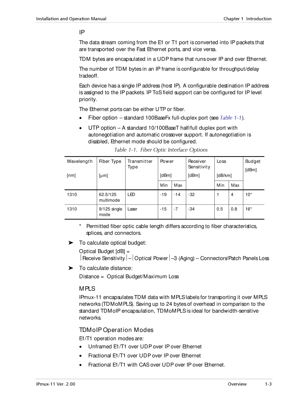
Table 1-1. Fiber Optic Interface Options
Wavelength | Fiber Type | Transmitter |
| Power |
| Receiver | Loss |
| Budget | |
|
| Type |
|
|
|
| Sensitivity |
|
| [dBm] |
[nm] | [μm] |
|
| [dBm] |
| [dBm] |
|
| ||
|
|
| [dB/km] |
| ||||||
|
|
|
|
|
|
|
|
|
|
|
|
|
|
| Min |
| Max |
| Min | Max |
|
|
|
|
|
|
|
|
|
|
|
|
1310 | 62.5/125 | LED |
| 1 | 4 | 10* | ||||
| multimode |
|
|
|
|
|
|
|
|
|
|
|
|
|
|
|
|
|
|
|
|
1310 | 9/125 single | Laser |
| 0.5 | 0.8 | 16* | ||||
| mode |
|
|
|
|
|
|
|
|
|
|
|
|
|
|
|
|
|
|
|
|
*Permitted fiber optic cable length differs according to fiber characteristics, splices, and connectors.
To calculate optical budget:
Optical Budget [dB] =
⏐Receive
To calculate distance:
Distance = Optical Budget/Maximum Loss
MPLS
TDMoIP Operation Modes
E1/T1 operation modes are:
•Unframed E1/T1 over UDP over IP over Ethernet
•Fractional E1/T1 over UDP over IP over Ethernet
•Fractional E1/T1 with CAS over UDP over IP over Ethernet.
Overview |