|
| Installation and Operation Manual | Chapter 4 Configuration |
|
| |
|
|
|
|
| ||
|
|
|
|
| ||
|
|
|
|
| ||
|
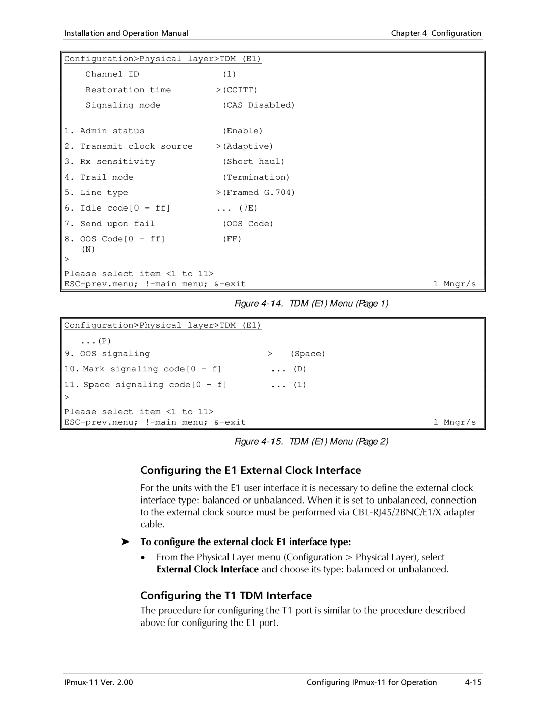
| Configuration>Physical layer>TDM (E1) |
|
| ||
|
|
| Channel ID | (1) |
|
|
|
|
| Restoration time | >(CCITT) |
|
|
|
|
| Signaling mode | (CAS Disabled) |
|
|
|
| 1. | Admin status | (Enable) |
|
|
|
| 2. | Transmit clock source | >(Adaptive) |
|
|
|
| 3. | Rx sensitivity | (Short haul) |
|
|
|
| 4. | Trail mode | (Termination) |
|
|
|
| 5. | Line type | >(Framed G.704) |
|
|
|
| 6. | Idle code[0 - ff] | ... (7E) |
|
|
|
| 7. | Send upon fail | (OOS Code) |
|
|
|
| 8. | OOS Code[0 - ff] | (FF) |
|
|
|
|
| (N) |
|
|
|
> |
|
|
Please select item <1 to 11> |
| 1 Mngr/s |
| ||
|
|
|
Figure | TDM (E1) Menu (Page 1) | |
|
|
|
Configuration>Physical layer>TDM (E1) |
|
|
...(P) |
|
|
9. OOS signaling | > | (Space) |
10. Mark signaling code[0 - f] | ... (D) | |
11. Space signaling code[0 - f] | ... (1) | |
> |
|
|
Please select item <1 to 11> |
| 1 Mngr/s |
| ||
|
|
|
Figure | TDM (E1) Menu (Page 2) | |
Configuring the E1 External Clock Interface
For the units with the E1 user interface it is necessary to define the external clock interface type: balanced or unbalanced. When it is set to unbalanced, connection to the external clock source must be performed via
To configure the external clock E1 interface type:
•From the Physical Layer menu (Configuration > Physical Layer), select External Clock Interface and choose its type: balanced or unbalanced.
Configuring the T1 TDM Interface
The procedure for configuring the T1 port is similar to the procedure described above for configuring the E1 port.
Configuring |