Chapter 3 OperationInstallation and Operation Manual
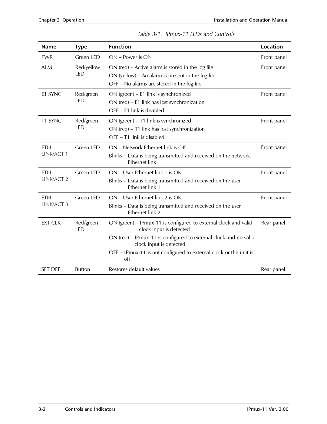
Table 3-1. IPmux-11 LEDs and Controls
Name | Type | Function | Location |
|
|
|
|
PWR | Green LED | ON – Power is ON | Front panel |
|
|
|
|
ALM | Red/yellow | ON (red) – Active alarm is stored in the log file | Front panel |
| LED | ON (yellow) – An alarm is present in the log file |
|
|
| OFF – No alarms are stored in the log file |
|
|
|
|
|
E1 SYNC | Red/green | ON (green) – E1 link is synchronized | Front panel |
| LED | ON (red) – E1 link has lost synchronization |
|
|
| OFF – E1 link is disabled |
|
|
|
|
|
T1 SYNC | Red/green | ON (green) – T1 link is synchronized | Front panel |
| LED | ON (red) – T1 link has lost synchronization |
|
|
| OFF – T1 link is disabled |
|
|
|
|
|
ETH | Green LED | ON – Network Ethernet link is OK | Front panel |
LINK/ACT 1 |
| Blinks – Data is being transmitted and received on the network |
|
|
| Ethernet link |
|
|
|
|
|
ETH | Green LED | ON – User Ethernet link 1 is OK | Front panel |
LINK/ACT 2 |
| Blinks – Data is being transmitted and received on the user |
|
|
| Ethernet link 1 |
|
|
|
|
|
ETH | Green LED | ON – User Ethernet link 2 is OK | Front panel |
LINK/ACT 3 |
| Blinks – Data is being transmitted and received on the user |
|
|
| Ethernet link 2 |
|
|
|
|
|
EXT CLK | Red/green | ON (green) – | Rear panel |
| LED | clock input is detected |
|
|
| ON (red) – |
|
|
| clock input is detected |
|
|
| OFF – |
|
|
| off |
|
|
|
|
|
SET DEF | Button | Restores default values | Rear panel |
|
|
|
|
Controls and Indicators |