CONFIGURING THE SWITCH
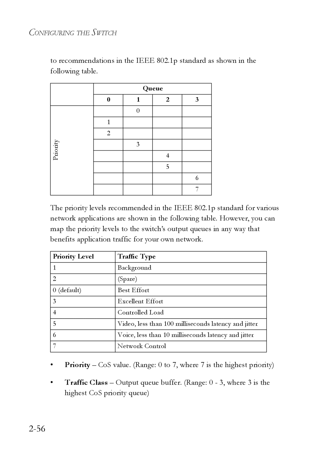
to recommendations in the IEEE 802.1p standard as shown in the following table.
|
|
| Queue |
| |
| 0 | 1 |
| 2 | 3 |
|
|
|
|
|
|
|
| 0 |
|
|
|
|
|
|
|
|
|
| 1 |
|
|
|
|
|
|
|
|
|
|
| 2 |
|
|
|
|
Priority |
|
|
|
|
|
| 3 |
|
|
| |
|
|
|
|
| |
|
|
| 4 |
| |
|
|
|
|
|
|
|
|
|
| 5 |
|
|
|
|
|
|
|
|
|
|
|
| 6 |
|
|
|
|
|
|
|
|
|
|
| 7 |
|
|
|
|
|
|
The priority levels recommended in the IEEE 802.1p standard for various network applications are shown in the following table. However, you can map the priority levels to the switch’s output queues in any way that benefits application traffic for your own network.
Priority Level | Traffic Type |
1 | Background |
|
|
2 | (Spare) |
|
|
0 (default) | Best Effort |
|
|
3 | Excellent Effort |
|
|
4 | Controlled Load |
|
|
5 | Video, less than 100 milliseconds latency and jitter |
|
|
6 | Voice, less than 10 milliseconds latency and jitter |
|
|
7 | Network Control |
|
|
•Priority – CoS value. (Range: 0 to 7, where 7 is the highest priority)
•Traffic Class – Output queue buffer. (Range: 0 - 3, where 3 is the highest CoS priority queue)