Getting Started
TANDBERG VIDEO COMMUNICATION SERVER ADMINISTRATOR GUIDE
What’s in the Box? | Installation Site Preparations | General Installation Precautions |
To avoid damage to the unit during transportation, the TANDBERG VCS is delivered in a special shipping box, which should contain the following components:
•TANDBERG VCS
•CD containing VCS Administrator Guide and other documentation
•Installation Sheet
•Registration card
•
•Cables:
•power cables
•ethernet cable
•shielded serial cable
Please report any discrepancies to your TANDBERG representative immediately.
A brief yet detailed description of the procedure to get you up and going can be found in the Installation Sheet accompanying your TANDBERG product.
•Make sure that the VCS is accessible and that all cables can be easily connected.
•For ventilation: leave a space of at least 10cm (4 inches) behind the VCS’s rear panel and 10cm (4 inches) in front of the front panel.
•The room in which you install the VCS should have an ambient temperature between 0ºC and 35ºC (32ºF and 95ºF) and between 10% and 90%
•Do not place heavy objects directly on top of the VCS.
•Do not place hot objects directly on top, or directly beneath the VCS.
•Use a grounded AC power outlet for the VCS.
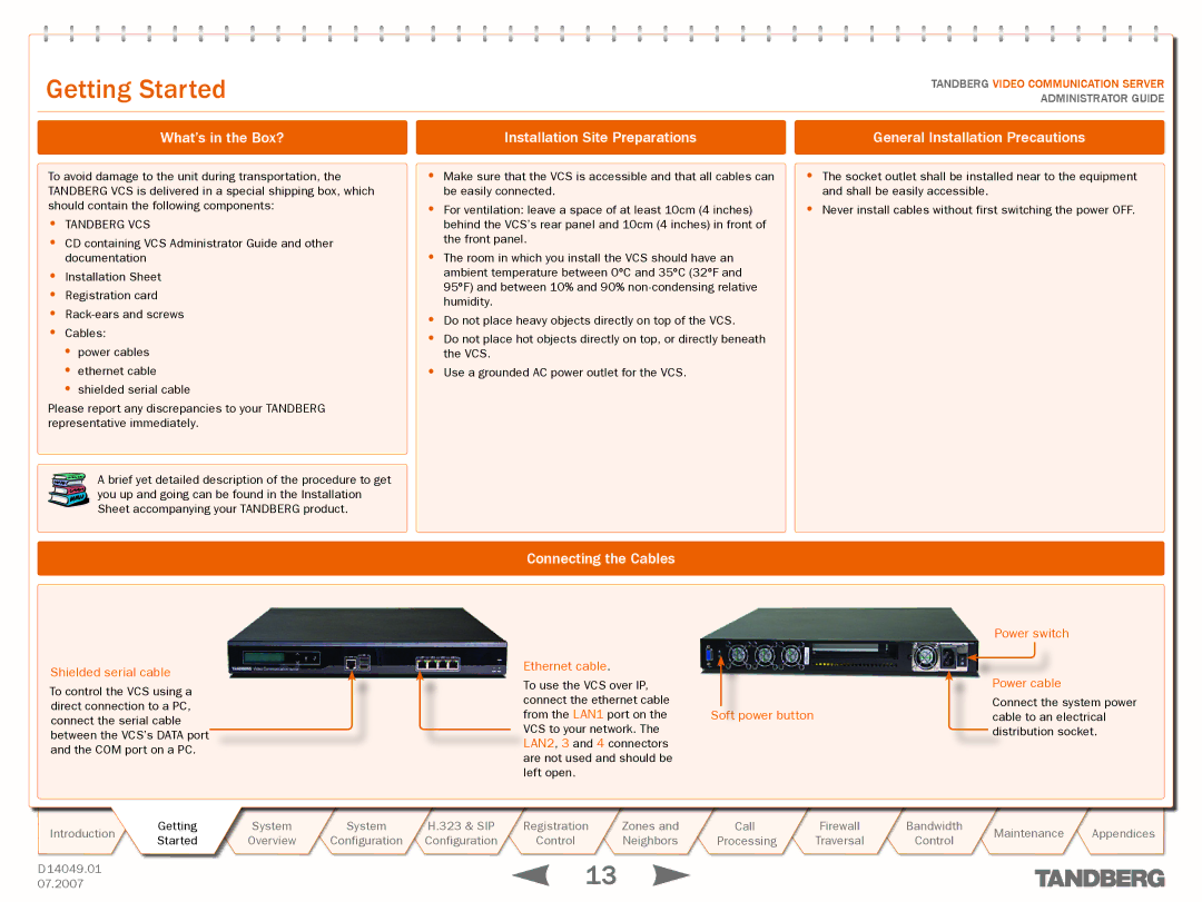
Connecting the Cables
•The socket outlet shall be installed near to the equipment and shall be easily accessible.
•Never install cables without first switching the power OFF.
Shielded serial cable
To control the VCS using a direct connection to a PC, connect the serial cable between the VCS’s DATA port and the COM port on a PC.
Ethernet cable.
To use the VCS over IP, connect the ethernet cable
from the LAN1 port on the Soft power button VCS to your network. The
LAN2, 3 and 4 connectors are not used and should be left open.
Power switch
Power cable
Connect the system power cable to an electrical distribution socket.
Introduction | Getting | System | System | H.323 & SIP | Registration | Zones and | Call | Firewall | Bandwidth | Maintenance | Appendices | |
Started | Overview | Configuration | Configuration | Control | Neighbors | Processing | Traversal | Control | ||||
|
|
| ||||||||||
D 14049.01 |
|
|
|
| 13 |
|
|
|
|
|
| |
07.2007 |
|
|
|
|
|
|
|
|
|
|