Manuals
/
Teledyne
/
Household Appliance
/
Water System
Teledyne
manual
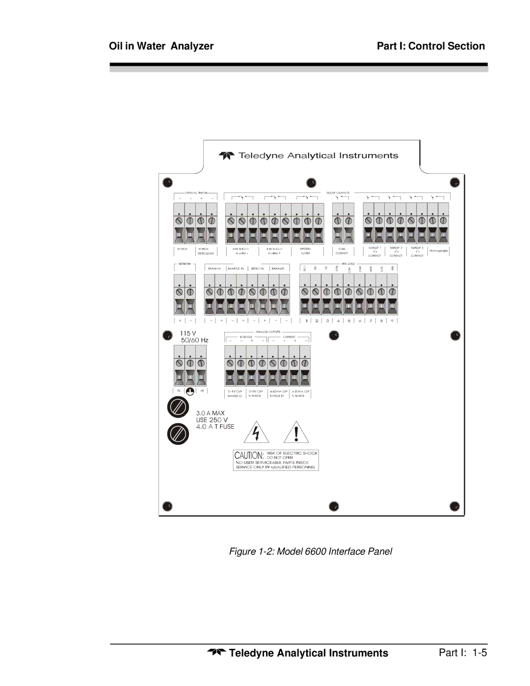
Model 6600 Interface Panel
Models:
6600
1
13
151
151
Download
151 pages
30.8 Kb
10
11
12
13
14
15
16
17
Page 13
Image 13
Oil in Water Analyzer
Part I: Control Section
Figure
1-2:
Model 6600 Interface Panel
Teledyne Analytical Instruments
Part I:
1-5
Page 12
Page 14
Page 13
Image 13
Page 12
Page 14
Contents
Teledyne Analytical Instruments
Oil in Water Analyzer
Copyright 1999 Teledyne Analytical Instruments
Model
Iii
Table of Contents
Model Teledyne Analytical Instruments
Part I Control Section
Model
Ii Part
Installation
Operation
Part I
Maintenance
Appendix
Model 6600 Oil in Water Analyzer
Iv Part
Oil in Water Analyzer Part I Control Section
Overview
Operator Interface
Main Features of the Analyzer
Introduction Model
ESCAPE/ENTER Switch
Model 6600 Controls, Indicators, and Connectors
Model 6600 Interface Panel
Control Section Interface Panel
Electrical Connections
Unpacking the Control/Analysis Unit
115VAC
Installation Model
Analog Output Connections
Examples
10.4
Range Voltage Current mA
Alarm Relays
Part
Data Carrier Detect
RS-232 Sig RS-232 Pin Purpose
Parameter Setting
Command Description
Testing the System
Part
Introduction
Using the Controls
Oil in Water Analyzer Operation
Mode/Function Selection
Operation Model
Hierarchy of System Functions and Subfunctions
System Function
Setting up an AUTO-CAL
EnteringthePassword
Password Protection
Installing or Changing the Password
Logging Out
System Self-Diagnostic Test
Checking Linearity with Algorithm
Operation Model Model Screen
Setting 90% Response time Seconds
Digital Filter Setup
Set Ultra Sonic Homogenizer on
Homogenizer Function Setup
Hold/Track Setup
Analog 4-20mA Output Calibartion
Operation Model Calibration/Hold Timer Setup
Manual control of filter and solenoids
Algorithm Application Model Outcal Anlz
Algorithmapplcation Model Outcal Anlz
Zero and Span Functions
Zero Cal
Auto Mode Zeroing
Manual Mode Zeroing
Zero Offset Calibration
Detector Failure
Spanning
How the offset value is selected
Manual Mode Spanning
Auto Mode Spanning
Oil in Water Analyzer Operation Span Cal
Alarms Function
Oil in Water Analyzer Operation
Range Select Function
Auto Screen
Precautions
Illustrates these schemes graphically
Analyze Function
Programming
Oil in Water Analyzer Operation Set Range Screen
Curve Algorithm Screen
Auto Mode Linearization
Ppm SO2 InputØ
Part I Control Section Maintenance
Fuse Replacement
Maintenance Model 6600 Oil in Water Analyzer
System Self Diagnostic Test
Power
Analog
Preamp
Major Internal Components
Detector
Side View Open Door
Part II Analysis Unit
Part II Analysis Section Control/Analysis Unit
Ii Part
Part II
Iv Part
Oil in Water Analyzer Operational Theory
Method of Analysis
Operational Theory Model
Optical Bench
Photometer Amplifier
Automatic Zero System
Zero drift may occur in the following cases
System Description
Source Module
Photometer
Detector Module
Sample Cell
Sample Systems
Unpacking the Analyzer
Installing and Connecting the Analyzer
Oil in Water Analyzer Part II Analysis Unit
User Connections
Signal and Alarm Output Connections
Installation Model Electrical Power Connections
Compressed Air Supply
Pipe Connections
Calibration Calibration Fluids
Method One
Calibration
Oil in Water Analyzer Maintenance
Routine Maintenance
System Visual Check and Response Procedure
Automatic operation and routine operational duties
Routine Maintenance
Maintenance Model
Suggested Preventive Maintenance Schedule
Power Supply Test Points
Service Procedures and Adjustments Electronics
Setup of the Signal Processing Front-End Amplifiers
Oscilloscope Display of the I to E Converter Output
Part
Inverting Amplifier
Setup of the Logarithmic Amplifier
Interface Board Terminals Strip
Battery-Powered Oscilloscope Synchronization Point
Part
Oil in Water Analyzer Maintenance
Part
Part III Oil in Water
Part III
Model 6620 Oil in Water Analyzer Table of Contents
Part III
Model 6620 Oil in Water Analyzer
Oil in Water Part
Introduction
Optical Bench
Method of Analysis
Photometer Amplifier
Part Model
Part III
Automatic Zero System
From B71046-0 or customer’s piping schematic
Oil in Water Piping Diagram B71046
Part
Part III
System Description
Source Module
Photometer
Sample Cell
Control/Analysis Unit
Detector Module
Part III Teledyne Analytical Instruments
Sampling System Sample Water Preconditioning System
Electrical Connections
Pressurized Inlet Sample Delivery
Zero Water Preconditioning System
Homogenizing
Ultra clean process applications for leaks into the like
Automatic Sample Cell Cleaning System
Entering the zero offset
Recorder Requirement
Signal Outputs
Amplifier PCB
Process Alarm System
Auto Zero Circuit
Detector Fail Check Detector signal
Signal Failure Alarm
Installation
Signal and Alarm Output Connections
Electrical Power Connections
User Connections
Compressed Air Supply
Safe Vent Drainage
Sample Delivery System
Electronics Check
Installation Check
Sample Delivery Check
Electrical Check
Preparation for Calibration
Manual Sample Introduction
Required Calibration Equipment
Acquisition of Representative Sample Water
Acquisition of Representative Oil Sample
Oscilloscope Display of the I to E Converter Output
Background Signal Level Determination
Part III
Part Model
Zero Fluid Preparation
Calibration with Prepared Sample
Span Fluid Preparation
Calibration
Setup of Internal Span Flag Calibration
SpanFilter
Calibration by Correlation with Laboratory Analysis
Sample System
Part III
Calibration of the ultrasonic homogenizer
Correlation
HomogenizerTuning
Automatic Operation and Routine Operational Duties
Electronics Set-up for Automatic Operation
Routine Maintenance
System Visual Check and Response Procedure
Monthly or 6 weeks maximum
Daily
Set up of the Signal Processing Front End Amplifiers
Service Procedures and Adjustments
Set Up of the I to E Converter
Integrated Reference and Measuring Signals
Set Up of the Logarithmic Amplifier
Inverting Amplifier
Sample Cell Maintenance
Zero Filter Replacement
Sample System Maintenance
316 Zero Filter Cleaning Procedure
Phototube Replacement
Lamp Replacement
Lamp Refuses to Light
Troubleshooting Section
Sample Pump Failure
Zero Drift Problems
Site requirements
Installation
Part Model
Sample Connections
Drawings
Start up of System
Allow warm-up for 1 hour
Set up for Automatic Sampling Sample System
Automatic Operation and Routine Duties
Oil in Water Part Teledyne Analytical Instruments
Operating Temperature 0-50oC
Specifications
Oil in Water Analyzer Appendix
Appendix Models
QtyP/NDescription
Recommended 2-Year Spare Parts List
Generic Drawing List
Drawing List See manual addendum
Top
Page
Image
Contents