Oil in Water Analyzer | Operation 3 | |
|
|
|
|
|
|
|
|
|

 System
D i g _ f i l t | Set | Digital |
|
|
|
|
|
|
| |
Filter |
|
|
|
|
|
|
| |||
|
|
|
|
|
|
|
| |||
|
|
|
|
| ||||||
Progress | Results |
|
|
|
|
| ||||
|
|
|
|
|
| |||||
P W D | Enter | C h a n g e | C h a n g e | Verify | Enter |
| ||||
Password | Yes/No | Password | Password |
| ||||||
|
|
|
| |||||||
L O G O U T | Secure | System |
|
|
|
|
|
|
| |
setup | not |
|
|
|
|
|
|
| ||
|
| allowed |
|
|
|
|
|
|
| |
M O R E |
|
|
|
|
|
|
|
|
|
|
AUTOCAL | Span/Zero status | Span/Zero timing | Enter |
|
|
|
| |||
and |
| <>setup | and on/off |
|
|
|
| |||
|
|
|
|
|
|
| ||||
H M G N Z R | Set | Ultrasonic | Enter |
|
|
|
|
| ||
H o m o g e n i z e r |
|
|
|
|
| |||||
| ON/OFF |
|
|
|
|
|
|
| ||
TRACK or | Set | track or |
|
|
|
|
|
|
| |
H O L D | hold | output |
|
|
|
|
|
|
| |
CAL - HOLD | Set | cal. | hold | Enter |
|
|
|
|
| |
TIMER | and | sample |
|
|
|
|
| |||
hold timer |
|
|
|
|
|
|
| |||
M O R E |
|
|
|
|
|
|
|
|
|
|
|
|
|
|
|
|
| Verify data | Enter |
| |
|
|
|
|
|
|
| Points |
| ||
|
|
|
|
|
|
|
|
|
| |
ALGORITHM | Select | range | Display | gas use | S e l e c t |
| Enter | Enter | ||
and | range | Verify/Setup |
| Input/Output | ||||||
|
|
|
|
| ||||||
|
|
|
|
|
|
| Auto/ |
|
|
|
|
|
|
|
|
|
| M a n u a l |
|
|
|
|
|
|
| D e f i n e |
| linear Cal. |
|
|
| |
APPLICATION | Select | range | Enter |
|
|
|
| |||
A p p l i c a t i o n / |
| Enter | Span | Enter | ||||||
|
|
|
| R a n g e |
|
| gas | value | ||
|
|
|
|
|
|
|
|
| ||
M O D E L | Display | Enter |
|
|
|
|
| |||
Model/Version |
|
|
|
|
| |||||
OUTPUT_CAL
Zero Analog | Enter | |
Output | ||
|
C a l i b r a t e
A n a l o gEnter O u t p u t
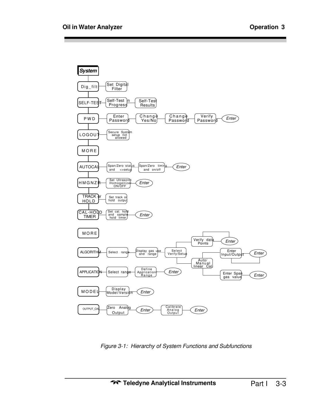
Figure 3-1: Hierarchy of System Functions and Subfunctions
Teledyne Analytical Instruments | Part I |
