3 Maintenance | Model 6600 | |
|
|
|
|
|
|
|
|
|
signals to control calibration solenoids and filters. To gain access to this terminals, the silkscreen cover must be removed. These terminals are wired in the factory.
WARNING: DANGEROUS HIGH VOLTAGES ARE PRESENT AT THESE TERMINALS. TRAINED PERSONNEL MUST REMOVE THE SILKSCREEN COVER ONLY. EXER- ![]() CISE EXTREME CAUTION.
CISE EXTREME CAUTION.
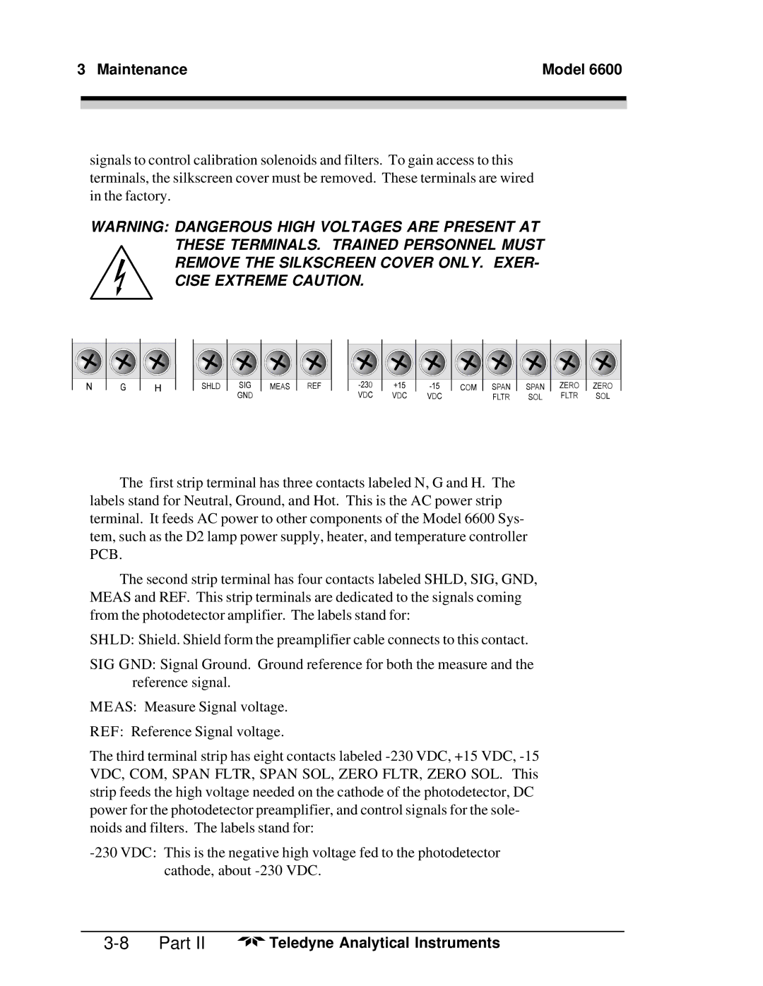
The first strip terminal has three contacts labeled N, G and H. The labels stand for Neutral, Ground, and Hot. This is the AC power strip terminal. It feeds AC power to other components of the Model 6600 Sys- tem, such as the D2 lamp power supply, heater, and temperature controller PCB.
The second strip terminal has four contacts labeled SHLD, SIG, GND, MEAS and REF. This strip terminals are dedicated to the signals coming from the photodetector amplifier. The labels stand for:
SHLD: Shield. Shield form the preamplifier cable connects to this contact.
SIG GND: Signal Ground. Ground reference for both the measure and the reference signal.
MEAS: Measure Signal voltage.
REF: Reference Signal voltage.
The third terminal strip has eight contacts labeled
Part II | Teledyne Analytical Instruments |