1. General Adjustments – Copying, Printing and
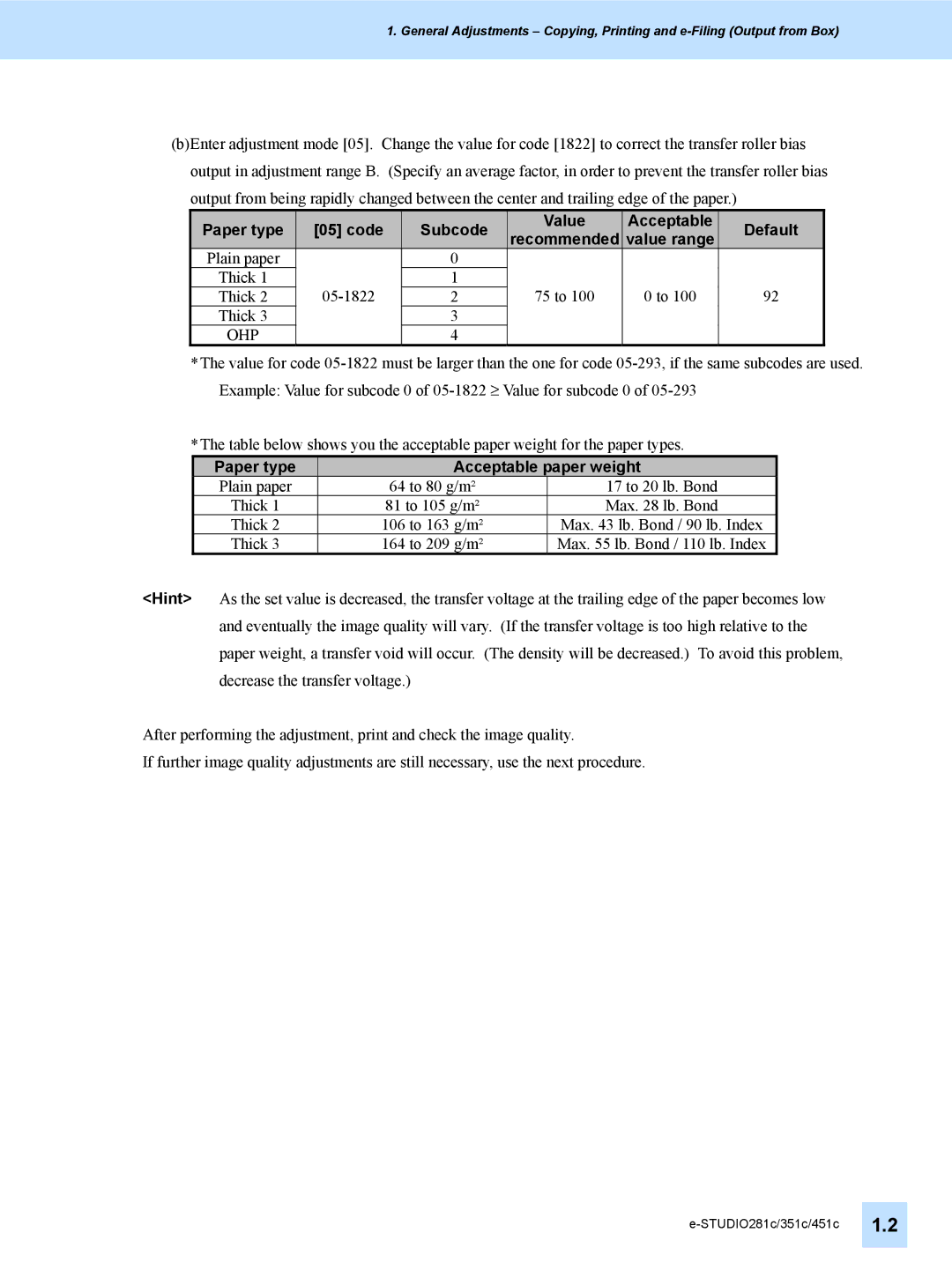
(b)Enter adjustment mode [05]. Change the value for code [1822] to correct the transfer roller bias output in adjustment range B. (Specify an average factor, in order to prevent the transfer roller bias output from being rapidly changed between the center and trailing edge of the paper.)
| Paper type |
|
| [05] code |
|
| Subcode |
| Value | Acceptable |
| Default |
|
|
|
|
|
|
| recommended | value range |
|
| ||||
|
|
|
|
|
|
|
|
|
|
|
| ||
| Plain paper |
|
|
| 0 |
|
|
|
|
|
| ||
| Thick 1 |
|
| 1 |
| 75 to 100 | 0 to 100 | 92 |
| ||||
| Thick 2 |
| 2 |
|
| ||||||||
| Thick 3 |
|
|
| 3 |
|
|
|
|
|
| ||
| OHP |
|
|
| 4 |
|
|
|
|
|
| ||
*The value for code
*The table below shows you the acceptable paper weight for the paper types.
Paper type | Acceptable paper weight | |
Plain paper | 64 to 80 g/m² | 17 to 20 lb. Bond |
Thick 1 | 81 to 105 g/m² | Max. 28 lb. Bond |
Thick 2 | 106 to 163 g/m² | Max. 43 lb. Bond / 90 lb. Index |
Thick 3 | 164 to 209 g/m² | Max. 55 lb. Bond / 110 lb. Index |
<Hint> As the set value is decreased, the transfer voltage at the trailing edge of the paper becomes low and eventually the image quality will vary. (If the transfer voltage is too high relative to the paper weight, a transfer void will occur. (The density will be decreased.) To avoid this problem, decrease the transfer voltage.)
After performing the adjustment, print and check the image quality.
If further image quality adjustments are still necessary, use the next procedure.