CONTROLLER COMPONENTS AND OPTIONS
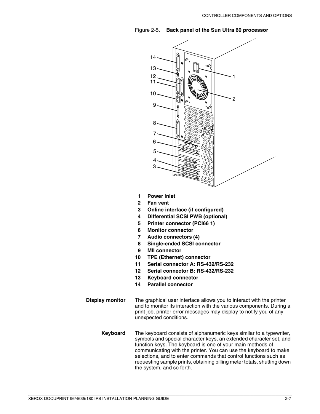
Figure 2-5. Back panel of the Sun Ultra 60 processor
1Power inlet
2Fan vent
3Online interface (if configured)
4Differential SCSI PWB (optional)
5Printer connector (PCI66 1)
6Monitor connector
7Audio connectors (4)
8Single-ended SCSI connector
9MII connector
10TPE (Ethernet) connector
11Serial connector A: RS-432/RS-232
12Serial connector B: RS-432/RS-232
13Keyboard connector
14Parallel connector
Display monitor The graphical user interface allows you to interact with the printer and to monitor its interaction with the various components. During a print job, printer error messages may display to notify you of any unexpected conditions.
Keyboard The keyboard consists of alphanumeric keys similar to a typewriter, symbols and special character keys, an extended character set, and function keys. The keyboard is one of your main methods of communicating with the printer. You can use the keyboard to make selections, and to enter commands that control functions such as requesting sample prints, obtaining billing meter totals, shutting down the system, and so forth.
XEROX DOCUPRINT 96/4635/180 IPS INSTALLATION PLANNING GUIDE |