CONTROLLER COMPONENTS AND OPTIONS
•
•
•
Cartridge tape drive (not shown): An optional 8 GB, 4 mm SCSI cartridge tape drive also is available for the IPS. Like the diskette and CD drives, this tape drive is not an input source for print jobs or for any other data or application. It provides the service representative with another means of loading system maintenance files or saving diagnostic information.
Caution: When installing a cartridge drive on an IPS with a host channel unit (HCU), the tape drive must be ![]()
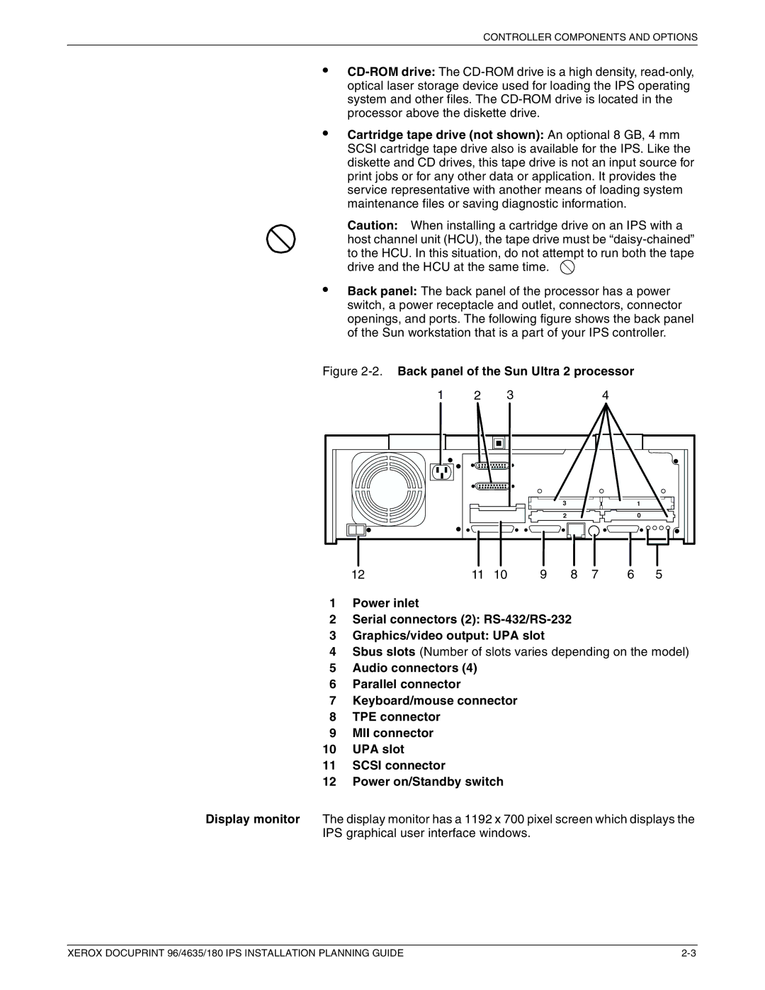
Back panel: The back panel of the processor has a power switch, a power receptacle and outlet, connectors, connector openings, and ports. The following figure shows the back panel of the Sun workstation that is a part of your IPS controller.
Figure |
| ||||||
1 | 2 | 3 |
|
|
| 4 |
|
|
|
|
| 3 |
|
| 1 |
|
|
|
| 2 |
|
| 0 |
12 | 11 | 10 | 9 | 8 | 7 | 6 | 5 |
1Power inlet
2Serial connectors (2):
3Graphics/video output: UPA slot
4Sbus slots (Number of slots varies depending on the model)
5Audio connectors (4)
6Parallel connector
7Keyboard/mouse connector
8TPE connector
9MII connector
10UPA slot
11SCSI connector
12Power on/Standby switch
Display monitor The display monitor has a 1192 x 700 pixel screen which displays the IPS graphical user interface windows.
XEROX DOCUPRINT 96/4635/180 IPS INSTALLATION PLANNING GUIDE |
