Manuals
/
Xerox
/
Computer Equipment
/
Printer
Xerox
180 IPS
manual
Models:
180 IPS
1
93
200
200
Download
200 pages
60.45 Kb
90
91
92
93
94
95
96
97
Specification
Install
Defaultnet
Dimension
Maintenance
Printer configurations
Problems
Delivery access requirements
Setup
Timeout
Page 93
Image 93
PRINTER SPECIFICATIONS AND REQUIREMENTS
XEROX DOCUPRINT 96/4635/180 IPS INSTALLATION PLANNING GUIDE
6-35
Page 92
Page 94
Page 93
Image 93
Page 92
Page 94
Contents
Xerox DocuPrint 96/4635/180 IPS Installation Planning Guide
Page
Laser safety
Operation safety
Ozone information
Xerox Docuprint 96/4635/180 IPS Installation Planning Guide
Table of Contents
Controller specifications and requirements
Printer specifications and requirements
System connections
Installation
Xerox support services
Supplies
Defining the printer to the host TCP/IP attachment
GLOSSARY-1 INDEX-1
Glossary Index
Page
Contents
Introduction
About this guide
This document uses the following conventions
Conventions
System overview
Product Overview
System components
System features
4635 IPS
NPS/IPS Dual Mode
Example of a check printed with Micr line U. S
Micr printing features
CMC7
Sixth Sense
Controller components and options
Controller hardware
Sun Ultra 2 workstation
Controller Components and Options
Back panel of the Sun Ultra 2 processor
Sun Ultra 60 workstation
Controller Components and Options
External cartridge tape drive
Controller Components and Options
IPS user interface screen
IPS user interface screen
Host Channel Unit-channel-attached systems only
Printer components
Printer components and options
Printer control console
Ready
96 printer-Inverter feeder/stacker only
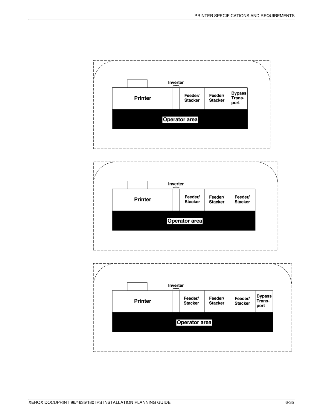
Printer configurations
4635/180 printer-Inverter feeder/stacker + feeder
Stacker + feeder/stacker
Stacker + feeder/stacker + feeder/stacker
Bypass transport
Printer options
Bypass transport printer configurations
Input enablement
Configurations supported
Configurations Input enablement kit and/or bypass transport
Input enablement kit only no bypass transport
Page
Installation
Preparing for installation
Responsibilities
Xerox responsibilities
Customer responsibilities
Service
Training
Site personnel
Applications
Review this Installation Planning Guide thoroughly
Prepare site
Installation planning checklist
Install
Post
Performing Routine Maintenance
Token Ring specifications
Ethernet specifications
Channel-attached specifications
Connectivity requirements
Page
Power requirements
Controller specifications and requirements
Sun Ultra 2 printer controller
Sun Ultra 60 printer controller
60 Hz wall outlet AC Hot ACH Earth Ground GND
Outlet configurations
Space requirements
Printer controller placement
Sun Ultra 2 workstation placement
Sun Ultra 2 fan and vent locations to keep clear Vent Fan
Sun Ultra 60 workstation placement
Controller Specifications and Requirements
HCU hardware for channel-attached systems
HCU placement channel-attached systems only
Interface to
Sun Ultra 2 60 Hz Power 8 ft
Sun Ultra 2 50 Hz
Sun Ultra 60 60 Hz
Controller Specifications and Requirements
Printer specifications and requirements
Printer outlet voltages-60 Hz
Nema 14-50R
Printer outlet voltages-50 Hz
Printer Specifications and Requirements
Environmental specifications
Printer placement
Printer with inverter feeder/stacker only
Dimension Specifications
Dimension Specifications
Dimension Specifications
Dimension Specifications
Bypass transport specifications
Bypass transport dimensions
Printer Specifications and Requirements
Bypass transport paper path Sheet path Exit rolls Floor
10.Input enablement paper path and dimensions
Configuration diagrams with bypass transport
38.8 98.6 cm 91.4 cm
Printer Specifications and Requirements
Space planning guidelines
Clearance space requirements
Shared space
Operator area Printer
14.Back-to-back shared service area space
15.Face-to-face shared service area space
16.Face-to-back shared space
Floor leveling
Delivery access requirements
Passage a Passage B
Turning radius
Turning radius for printer with separated components
Printer Specifications and Requirements
Printer Specifications and Requirements
Printer hardware specifications and requirements summary
12.Printer specifications and power requirements-96
4635 60 Hz Printer
Operating 4635
Transport
Bypass
Space planning templates
Page
Page
Page
Page
Page
Page
N e Grid Pattern 1/4 inch represents one foot
Page
Power cable lengths Length
System connections
Cable lengths
Cable locations
Channel attachments
Front
Installation process
Installation
Your responsibilities
Software licensing
Defining the IPS printer to the host
Ongoing maintenance
Routine maintenance
Meter reading and reporting
Supplies
Paper and other throughput stocks
Selecting paper
Supplies
Perforated paper Pre-cut or full tabs Carbonless paper
Paper width and printer performance
Throughput data 96 printer Pitch Paper width Speed
Throughput data 4635 printer Pitch Paper width Speed
Throughput data 180 printer Pitch Paper width Speed
Using small paper sizes in 8-pitch mode
Figure A-1.8-pitch mode paper sizes 4635 and 180 only
European papers
Figure A-2.3-pitch mode paper sizes
US Papers
Figure A-4.A3 297 by 420 mm paper feeding short edge feed
Figure A-7.B4 250 by 353 mm paper feeding long edge feed
B4 Papers
Figure A-9.Storing paper correctly
Paper care
Supplies
Cartons Hours
Centigrade
Dry ink
Other supplies
Fuser agent
Developer
Cartridge tapes
Diskettes
Micr Positioning and Dimension Gauge
Micr tools
Micr comparator
Paper and special stocks tables
Consumable supplies tables
Supplies
Description Part number
Table A-5.Stocks list for 96/4635/180 printers
Tab stock
Labels Gummed
Straight collated singles forward, top down
Reverse collated singles bottom up
Table A-6.Carbonless stocks for 96/4635/180 printers
Supplies
Complete supplies list-96/4635/180 printers
Ordering supplies
Supplies
Page
Supplies
Supplies
Xerox Customer Service Support Center
Xerox support services
Xerox Printing Systems Customer Support Center
Xerox Documentation and Software Services Xdss
Xerox Customer Documentation Catalog
Operator training
Xerox Font Center
Xerox Customer Education
Title
Related publications
Related Publications
Defining the channel-attached printer to the host
MVS parameters
Printer definitions for MVS versions earlier than
Printer definitions for MVS versions 4.1 and higher
Figure D-1.MVS hardware configuration definition panels
ES3090/9000 Input/Output Program User’s Guide #GC38
Figure D-2.OS/2 New Device window
OS/2 procedures
AIX procedures
VSE sample definitions
VM sample definitions
Defining the printer to the host TCP/IP attachment
MVS or OS/390 parameters
Software prerequisites MVS
Configuration steps MVS
Network configurations MVS
Configure the IPS printer for TCP/IP at the GUI
Configure the MVS CCU for the MVS host to MVS
Autostop
Proc
Haspfssm
Haspfssm Class
Table E-2.JES2 Initialization Dataset commands example
Msgdest JES
Fssname
Pname
System
Dynamic
Table E-4.JES3 initialization dataset commands example
Jname
ON/OFF
Example
Configure the printer in PSF/MVS
Logmode
Jobtrlr
Luname
Message
Pimsg
Setup
Portno
Psegdd
Trace
Timeout
Table E-6.PSF/MVS Printdev statement example
Configure TCP/IP for MVS for the printer
Considerations for configuring TCP/IP for MVS
Table E-8.TCP/IP Profile dataset statements example MVS
Defaultnet
Ping ip-address
Test the printer to ensure it prints from the MVS host
Defining the Printer to the Host TCP/IP Attachment
Problems
Correcting for printer performance issues MVS
Table E-11.Components to check for printer performance
LAN
Table E-12.MVS reference documentation
References
AS/400 parameters
Network configurations AS/400
Software prerequisites AS/400
Base
Configuration worksheet
Configuration steps AS/400
Table E-14.AS/400 configuration worksheet for IPS
Create the PSF/400 configuration
Create the printer device description AS/400
Table E-15.Create PSF Configuration screen AS/400
Create Device Desc Printer Crtdevprt
Ping ‘Remote Location’
Test the printer connection AS/400
Defining the Printer to the Host TCP/IP Attachment
References AS/400
Correcting for printer performance issues AS/400
Software prerequisites AIX
AIX parameters
Configuration steps-AIX
Network configurations AIX
IBM Print Services Facility for AIX AIX for Users of Print
Network configurations OS/2
OS/2 parameters
Software prerequisites OS/2
Table E-23.OS/2 configuration worksheet for IPS
Configuration steps OS/2
Configure the printer for TCP/IP in OS/2
Provide TCP/IP routing information, if necessary
Define the printer to PSF/2
Define a PSF/2 print queue for the printer optional
IPS UI
Test the printer connection in OS/2
Aprint asciifile DESTINATION=xeroxdev
If PSF/2 output for the IPS prints elsewhere
Correcting for printer performance issues OS/2
Problems OS/2
Table E-28.Components to check for printer performance
Table E-29.Reference documents OS/2 Title IBM order number
References OS/2
Page
Glossary
Multipliers are
Computer space equivalents are
Break page See header
GLOSSARY-3
Glossary
GLOSSARY-5
Glossary
GLOSSARY-7
Glossary
GLOSSARY-9
Glossary
GLOSSARY-11
Glossary
Software application
Glossary
GLOSSARY-15
Page
Numerics
Index
Ieee
Micr
JES2
PSF
Parameters, E-12statements example, E-13
Top
Page
Image
Contents