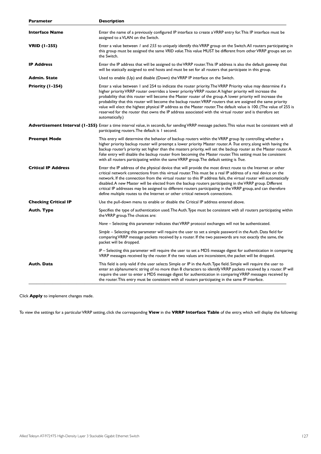
Parameter | Description |
|
Interface Name | Enter the name of a previously configured IP interface to create a VRRP entry for.This IP interface must be | |
VRID | assigned to a VLAN on the Switch. | |
Enter a value between 1 and 255 to uniquely identify this VRRP group on the Switch.All routers participating in | ||
| this group must be assigned the same VRID value.This value MUST be different from other VRRP groups set on | |
IP Address | the Switch. | |
Enter the IP address that will be assigned to the VRRP router.This IP address is also the default gateway that | ||
Admin. State | will be statically assigned to end hosts and must be set for all routers that participate in this group. | |
Used to enable (Up) and disable (Down) the VRRP IP interface on the Switch. | ||
Priority | Enter a value between 1 and 254 to indicate the router priority.The VRRP Priority value may determine if a | |
| higher priority VRRP router overrides a lower priority VRRP router.A higher priority will increase the | |
| probability that this router will become the Master router of the group.A lower priority will increase the | |
| probability that this router will become the backup router.VRRP routers that are assigned the same priority | |
| value will elect the highest physical IP address as the Master router.The default value is 100. (The value of 255 is | |
| reserved for the router that owns the IP address associated with the virtual router and is therefore set | |
| automatically.) | |
Advertisement Interval | ||
Preempt Mode | participating routers.The default is 1 second. | |
This entry will determine the behavior of backup routers within the VRRP group by controlling whether a | ||
| higher priority backup router will preempt a lower priority Master router.A True entry, along with having the | |
| backup router’s priority set higher than the masters priority, will set the backup router as the Master router.A | |
| False entry will disable the backup router from becoming the Master router.This setting must be consistent | |
Critical IP Address | with all routers participating within the same VRRP group.The default setting is True. | |
Enter the IP address of the physical device that will provide the most direct route to the Internet or other | ||
| critical network connections from this virtual router.This must be a real IP address of a real device on the | |
| network. If the connection from the virtual router to this IP address fails, the virtual router will automatically | |
| disabled.A new Master will be elected from the backup routers participating in the VRRP group. Different | |
| critical IP addresses may be assigned to different routers participating in the VRRP group, and can therefore | |
Checking Critical IP | define multiple routes to the Internet or other critical network connections. | |
Use the | ||
Auth. Type | Specifies the type of authentication used.The Auth.Type must be consistent with all routers participating within | |
| the VRRP group.The choices are: | |
| None – Selecting this parameter indicates that VRRP protocol exchanges will not be authenticated. | |
| Simple – Selecting this parameter will require the user to set a simple password in the Auth. Data field for | |
| comparing VRRP message packets received by a router. If the two passwords are not exactly the same, the | |
| packet will be dropped. | |
| IP – Selecting this parameter will require the user to set a MD5 message digest for authentication in comparing | |
Auth. Data | VRRP messages received by the router. If the two values are inconsistent, the packet will be dropped. | |
This field is only valid if the user selects Simple or IP in the Auth.Type field. Simple will require the user to | ||
| enter an alphanumeric string of no more than 8 characters to identify VRRP packets received by a router. IP will | |
| require the user to enter a MD5 message digest for authentication in comparing VRRP messages received by | |
| the router.This entry must be consistent with all routers participating in the same IP interface. |
|
Click Apply to implement changes made.
To view the settings for a particular VRRP setting, click the corresponding View in the VRRP Interface Table of the entry, which will display the following:
Allied Telesyn | 127 |
