A~H with their respective weight value: 8~1, the packets are sent in the following sequence:A1, B1, C1, D1, E1, F1, G1, H1,A2, B2, C2, D2, E2, F2, G2,A3, B3, C3, D3, E3, F3,A4, B4, C4, D4, E4,A5, B5, C5, D5,A6, B6, C6,A7, B7,A8,A1, B1, C1, D1, E1, F1, G1, H1.
For weighted
For weighted
mCaution: The Switch contains eight classes of service for each port on the Switch. One of these classes is reserved for internal use on the Switch and is therefore unconfigurable.All references in the following section regarding classes of service will refer to only the seven classes of service that may be used and configured by the Switch’s Administrator.
Bandwidth Control
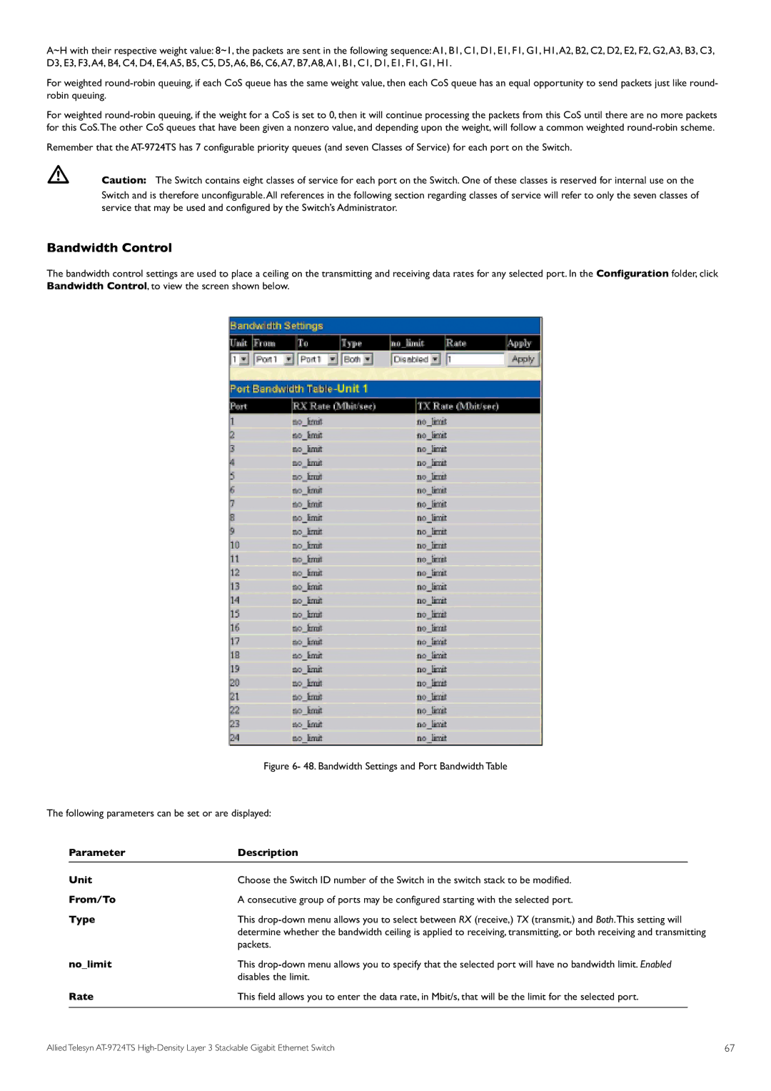
The bandwidth control settings are used to place a ceiling on the transmitting and receiving data rates for any selected port. In the Configuration folder, click Bandwidth Control, to view the screen shown below.
Figure 6- 48. Bandwidth Settings and Port Bandwidth Table
The following parameters can be set or are displayed:
Parameter | Description |
|
Unit | Choose the Switch ID number of the Switch in the switch stack to be modified. | |
From/To | A consecutive group of ports may be configured starting with the selected port. | |
Type | This | |
| determine whether the bandwidth ceiling is applied to receiving, transmitting, or both receiving and transmitting | |
no_limit | packets. | |
This | ||
Rate | disables the limit. | |
This field allows you to enter the data rate, in Mbit/s, that will be the limit for the selected port. |
| |
Allied Telesyn | 67 |
