The following fields can be set: |
|
| |
| Parameter | Description |
|
| Unit | Choose the Switch ID number of the Switch in the switch stack to be modified. | |
| From/To | These two fields allow you to specify the range of ports that will be included in the | |
| GVRP | are creating using the 802.1Q Static VLANs page. | |
| The Group VLAN Registration Protocol (GVRP) enables the port to dynamically become a member of a VLAN. | ||
| Ingress Check | GVRP is Disabled by default. | |
| This field can be toggled using the space bar between Enabled and Disabled. Enabled enables the port to | ||
|
| compare the VID tag of an incoming packet with the PVID number assigned to the port. If the two are different, | |
| Acceptable Frame Type | the port filters (drops) the packet. Disabled disables ingress filtering. Ingress Checking is Disabled by default. | |
| This field denotes the type of frame that will be accepted by the port.The user may choose between Tagged | ||
|
| Only, which means only VLAN tagged frames will be accepted, and Admit_All, which means both tagged and | |
| PVID | untagged frames will be accepted. Admit_All is enabled by default. | |
| The read only field in the GVRP Table shows the current PVID assignment for each port, which may be | ||
|
| manually assigned to a VLAN when created in the 802.1Q Static VLANs table.The Switch's default is to assign | |
|
| all ports to the default VLAN with a VID of 1.The PVID is used by the port to tag outgoing, untagged packets, | |
|
| and to make filtering decisions about incoming packets. If the port is specified to accept only tagged frames – as | |
|
| tagging, and an untagged packet is forwarded to the port for transmission, the port will add an 802.1Q tag using | |
|
| the PVID to write the VID in the tag.When the packet arrives at its destination, the receiving device will use the | |
|
| PVID to make VLAN forwarding decisions. If a packet is received by the port, and Ingress filtering is enabled, the | |
|
| port will compare the VID of the incoming packet to its PVID. If the two are unequal, the port will drop the | |
|
| packet. If the two are equal, the port will receive the packet. |
|
Click Apply to implement changes made. |
|
| |
6-15 Traffic Control
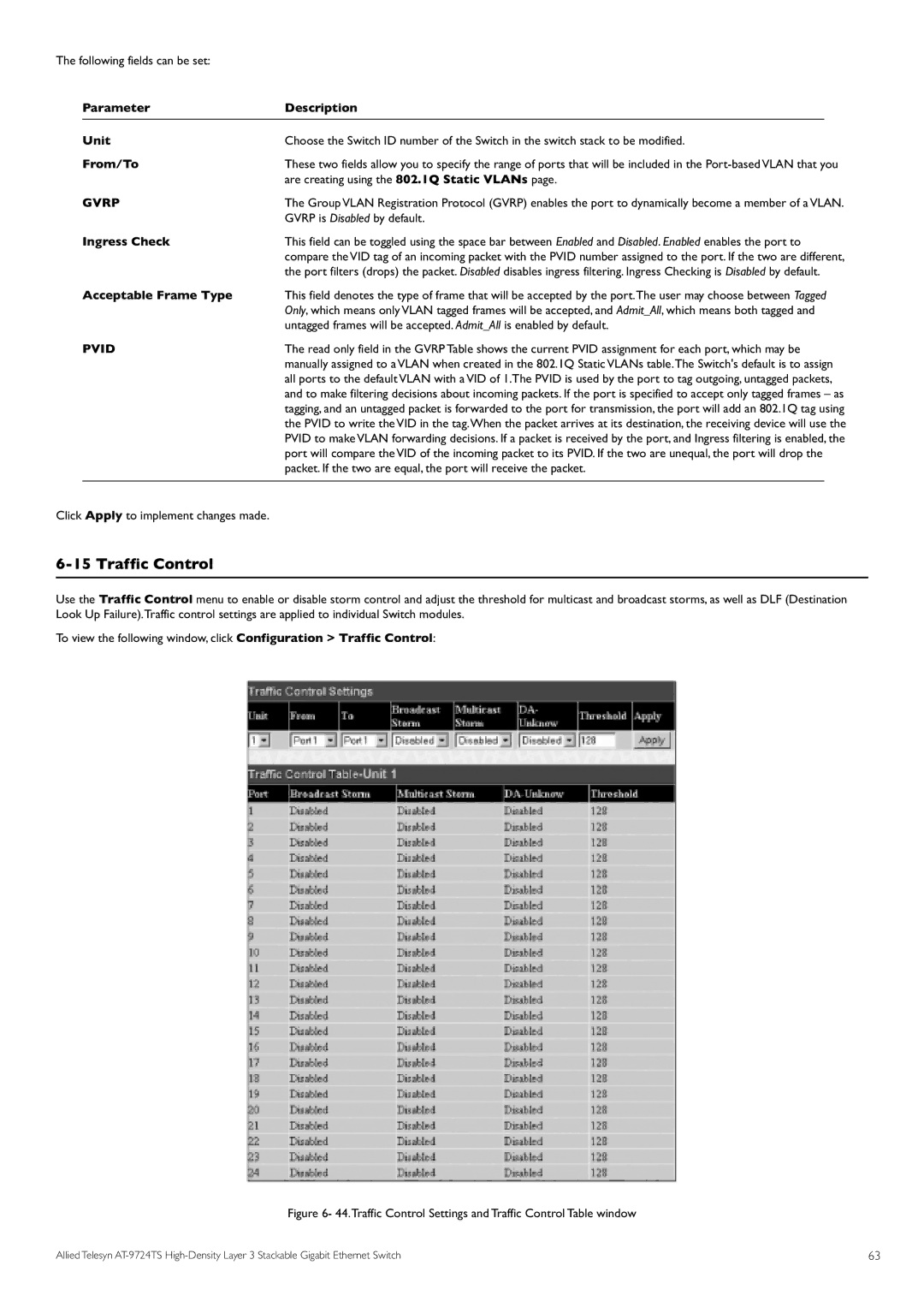
Use the Traffic Control menu to enable or disable storm control and adjust the threshold for multicast and broadcast storms, as well as DLF (Destination Look Up Failure).Traffic control settings are applied to individual Switch modules.
To view the following window, click Configuration > Traffic Control:
Figure 6- 44.Traffic Control Settings and Traffic Control Table window
Allied Telesyn | 63 |
