Electrical Installation | Interconnection wiring is required between the motor control, AC power source, motor, | |
| host control and any operator interface stations. Use only UL (cUL) listed closed loop | |
| connectors that are of appropriate size for wire gauge being used. Connectors are to be | |
| installed using crimp tool specified by the manufacturer of the connector. Only Class 1 | |
| wiring should be used. | |
| Baldor Series 22H controls feature UL approved adjustable motor overload protection | |
| suitable for motors rated at no less than 50% of the output rating of the control. Other | |
| governing agencies such as NEC may require separate | |
| installer of this equipment is responsible for complying with the National Electric Code | |
| and any applicable local codes which govern such practices as wiring protection, | |
| grounding, disconnects and other current protection. | |
Load Reactors | Line reactors may be used at the control output to the motor. When used this way, they are | |
| called Load Reactors. Load reactors serve several functions that include: | |
| S | Protect the control from a short circuit at the motor. |
| S | Limit the rate of rise of motor surge currents. |
| S | Slowing the rate of change of power the control delivers to the motor. |
| Load reactors should be installed as close to the control as possible. Select the load | |
| reactor that matches the full load amperes (FLA) stated on the nameplate of the motor | |
| you are using. | |
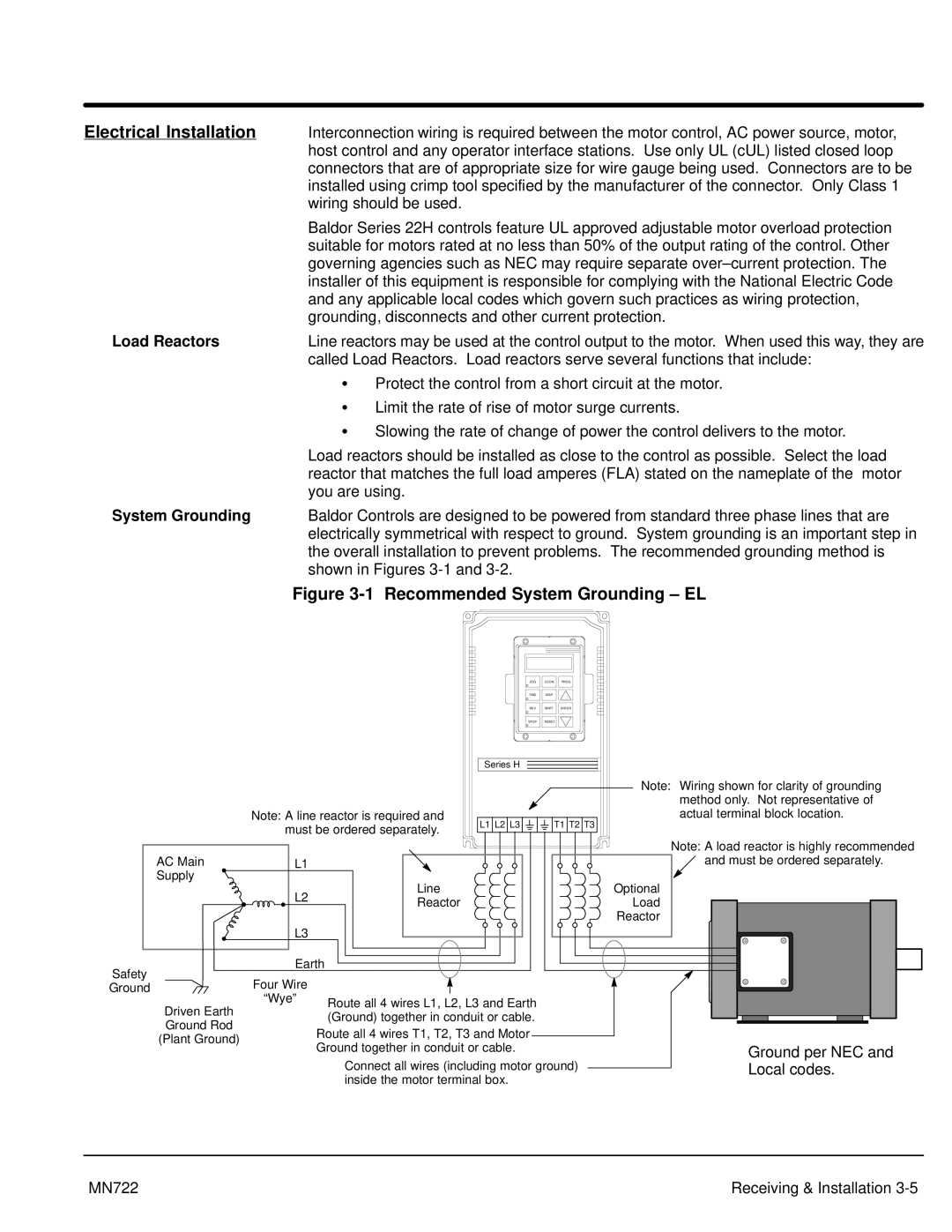
System Grounding | Baldor Controls are designed to be powered from standard three phase lines that are | |
| electrically symmetrical with respect to ground. System grounding is an important step in | |
| the overall installation to prevent problems. The recommended grounding method is | |
| shown in Figures | |
Figure 3-1 Recommended System Grounding – EL
JOG | LOCAL | PROG |
FWD | DISP |
|
REV | SHIFT | ENTER |
STOP | RESET |
|
Series H
|
|
|
|
| Note: Wiring shown for clarity of grounding |
|
|
|
|
| method only. Not representative of |
| Note: A line reactor is required and | L1 L2 L3 | T1 T2 T3 | actual terminal block location. | |
| must be ordered separately. |
| |||
|
|
|
| ||
|
|
|
|
| Note: A load reactor is highly recommended |
AC Main | L1 |
|
|
| and must be ordered separately. |
Supply |
| Line |
|
| Optional |
| L2 |
|
| ||
| Reactor |
|
| Load | |
|
|
|
| ||
|
|
|
|
| Reactor |
| L3 |
|
|
|
|
Safety | Earth |
|
|
| |
Four Wire |
|
|
|
| |
Ground |
|
|
|
| |
Driven Earth | “Wye” | Route all 4 wires L1, L2, L3 and Earth |
|
| |
|
|
| |||
| (Ground) together in conduit or cable. |
|
| ||
Ground Rod |
|
|
| ||
| Route all 4 wires T1, T2, T3 and Motor |
|
| ||
(Plant Ground) |
|
|
| ||
| Ground together in conduit or cable. |
| Ground per NEC and | ||
|
|
| |||
|
| Connect all wires (including motor ground) | Local codes. | ||
|
| inside the motor terminal box. |
|
| |
MN722 | Receiving & Installation |