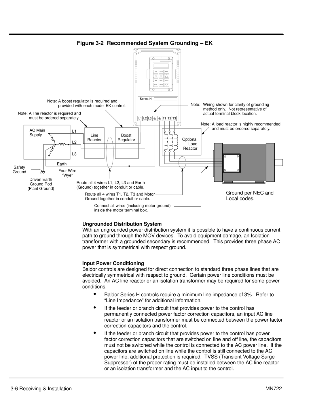
Figure 3-2 Recommended System Grounding – EK
JOG | LOCAL | PROG |
FWD | DISP |
|
REV | SHIFT | ENTER |
STOP | RESET |
|
Note: A boost regulator is required and | Series H |
| ||
| Note: Wiring shown for clarity of grounding | |||
| provided with each model EK control. | |||
Note: A line reactor is required and |
|
| method only. Not representative of | |
|
| actual terminal block location. | ||
must be ordered separately. |
| L1 L2 L3 | T1 T2 T3 | |
|
|
|
| Note: A load reactor is highly recommended |
AC Main | L1 |
|
| and must be ordered separately. |
|
|
| ||
Supply |
| Line | Boost | Optional |
| L2 | Reactor | Regulator | |
|
|
| Load | |
|
|
|
| |
|
|
|
| Reactor |
| L3 |
|
|
|
Safety | Earth |
|
|
|
Four Wire |
|
|
| |
Ground |
|
|
| |
Driven Earth | “Wye” |
|
|
|
Route all 4 wires L1, L2, L3 and Earth |
| |||
Ground Rod |
| |||
(Ground) together in conduit or cable. |
| |||
(Plant Ground) |
| |||
|
|
| Ground per NEC and | |
|
| Route all 4 wires T1, T2, T3 and Motor | ||
|
| Ground together in conduit or cable. | Local codes. | |
Connect all wires (including motor ground) inside the motor terminal box.
Ungrounded Distribution System
With an ungrounded power distribution system it is possible to have a continuous current path to ground through the MOV devices. To avoid equipment damage, an Isolation transformer with a grounded secondary is recommended. This provides three phase AC power that is symmetrical with respect ground.
Input Power Conditioning
Baldor controls are designed for direct connection to standard three phase lines that are electrically symmetrical with respect to ground. Certain power line conditions must be avoided. An AC line reactor or an isolation transformer may be required for some power conditions.
SBaldor Series H controls require a minimum line impedance of 3%. Refer to “Line Impedance” for additional information.
SIf the feeder or branch circuit that provides power to the control has permanently connected power factor correction capacitors, an input AC line reactor or an isolation transformer must be connected between the power factor correction capacitors and the control.
SIf the feeder or branch circuit that provides power to the control has power factor correction capacitors that are switched on line and off line, the capacitors must not be switched while the control is connected to the AC power line. If the capacitors are switched on line while the control is still connected to the AC power line, additional protection is required. TVSS (Transient Voltage Surge Suppressor) of the proper rating must be installed between the AC line reactor or an isolation transformer and the AC input to the control.
MN722 |
