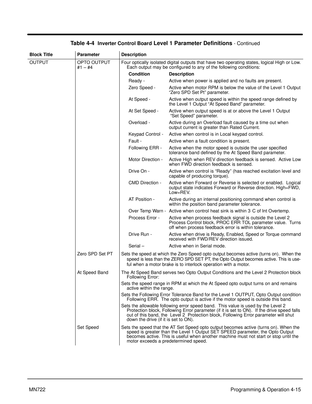
Table 4-4 Inverter Control Board Level 1 Parameter Definitions - Continued
Block Title | Parameter | Description |
|
|
|
| |
OUTPUT | OPTO OUTPUT | Four optically isolated digital outputs that have two operating states, logical High or Low. | |
| #1 – #4 | Each output may be configured to any of the following conditions: | |
|
| Condition | Description |
|
| Ready - | Active when power is applied and no faults are present. |
|
| Zero Speed - | Active when motor RPM is below the value of the Level 1 Output |
|
|
| “Zero SPD Set Pt” parameter. |
|
| At Speed - | Active when output speed is within the speed range defined by |
|
|
| the Level 1 Output “At Speed Band” parameter. |
|
| At Set Speed - | Active when output speed is at or above the Level 1 Output |
|
|
| “Set Speed” parameter. |
|
| Overload - | Active during an Overload fault caused by a time out when |
|
|
| output current is greater than Rated Current. |
|
| Keypad Control - | Active when control is in Local keypad control. |
|
| Fault - | Active when a fault condition is present. |
|
| Following ERR - | Active when the motor speed is outside the user specified |
|
|
| tolerance band defined by the At Speed Band parameter. |
|
| Motor Direction - | Active High when REV direction feedback is sensed. Active Low |
|
|
| when FWD direction feedback is sensed. |
|
| Drive On - | Active when control is “Ready” (has reached excitation level and |
|
|
| capable of producing torque). |
|
| CMD Direction - | Active when Forward or Reverse is selected or enabled. Logical |
|
|
| output state indicates Forward or Reverse direction. High=FWD, |
|
|
| Low=REV. |
|
| AT Position - | Active during an internal positioning command when control is |
|
|
| within the position band parameter tolerance. |
|
| Over Temp Warn - Active when control heat sink is within 3° C of Int Overtemp. | |
|
| Process Error - | Active when process feedback signal is outside the Level 2 |
|
|
| Process Control block, PROC ERR TOL parameter value. Turns |
|
|
| off when process feedback error is within tolerance. |
|
| Drive Run - | Active when drive is Ready, Enabled, Speed or Torque command |
|
|
| received with FWD/REV direction issued. |
|
| Serial – | Active when in Serial mode. |
| Zero SPD Set PT | Sets the speed at which the Zero Speed opto output becomes active (turns on). When the | |
|
| speed is less than the ZERO SPD SET PT, the Opto Output becomes active. This is use- | |
|
| ful when a motor brake is to interlock operation with a motor. | |
| At Speed Band | The At Speed Band serves two Opto Output Conditions and the Level 2 Protection block | |
|
| Following Error: |
|
|
| Sets the speed range in RPM at which the At Speed opto output turns on and remains | |
|
| active within the range. | |
|
| Sets the Following Error Tolerance Band for the Level 1 OUTPUT, Opto Output condition | |
|
| Following ERR. The opto output is active if the motor speed is outside this band. | |
|
| Sets the allowable following error speed band. This value is used by the Level 2 | |
|
| Protection block, Following Error parameter (if it is set to ON). If the drive speed falls | |
|
| out of this band, the | Level 2 Protection block, Following Error parameter will shut |
|
| down the drive (if it is set to ON). | |
| Set Speed | Sets the speed that the AT Set Speed opto output becomes active (turns on). When the | |
|
| speed is greater than the Level 1 Output SET SPEED parameter, the Opto Output | |
|
| becomes active. This is useful when another machine must not start or stop until the | |
|
| motor exceeds a predetermined speed. | |
|
|
|
|
MN722 | Programming & Operation |