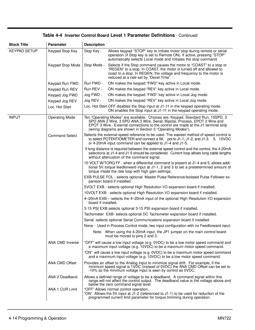
Table 4-4 Inverter Control Board Level 1 Parameter Definitions - Continued
Block Title | Parameter | Description | |
|
|
|
|
KEYPAD SETUP | Keypad Stop Key | Stop Key - Allows keypad “STOP” key to initiate motor stop during remote or serial | |
|
| operation (if Stop key is set to Remote ON). If active, pressing “STOP” | |
|
| automatically selects Local mode and initiates the stop command. | |
| Keypad Stop Mode | Stop Mode - Selects if the Stop command causes the motor to “COAST” to a stop or | |
|
| “REGEN” to a stop. In COAST, the motor is turned off and allowed to | |
|
| coast to a stop. In REGEN, the voltage and frequency to the motor is | |
|
| reduced at a rate set by “Decel Time”. | |
| Keypad Run FWD | Run FWD - ON makes the keypad “FWD” key active in Local mode. | |
| Keypad Run REV | Run REV - ON makes the keypad “REV” key active in Local mode. | |
| Keypad Jog FWD | Jog FWD - ON makes the keypad “FWD” key active in Local Jog mode. | |
| Keypad Jog REV | Jog REV - ON makes the keypad “REV” key active in Local Jog mode. | |
| Loc. Hot Start | Loc. Hot Start OFF disables the Stop input at | |
|
| ON enables the Stop input at | |
|
|
|
|
INPUT | Operating Mode | Ten “Operating Modes” are available. Choices are: Keypad, Standard Run, 15SPD, 3 | |
|
| SPD ANA 2 Wire, 3 SPD ANA 3 Wire, Serial, Bipolar, Process, EPOT 2 Wire and | |
|
| EPOT 3 Wire. External connections to the control are made at the J1 terminal strip | |
|
| (wiring diagrams are shown in Section 3 “Operating Modes”). | |
| Command Select | Selects the external speed reference to be used. The easiest method of speed control is | |
|
| to select POTENTIOMETER and connect a 5KW pot to | |
|
| or | |
|
| If long distance is required between the external speed control and the control, the | |
|
| selections at | |
|
| without attenuation of the command signal. | |
|
| 10 VOLT W/TORQ FF - when a differential command is present at | |
|
| tional 5V torque feedforward input at | |
|
| torque inside the rate loop with high gain settings. | |
|
| EXB PULSE FOL - selects optional Master Pulse Reference/Isolated Pulse Follower ex- | |
|
| pansion board if installed. | |
|
| 5VOLT EXB - selects optional High Resolution I/O expansion board if installed. | |
|
| 10VOLT EXB - selects optional High Resolution I/O expansion board if installed. | |
|
| ||
|
| board if installed. | |
|
| ||
|
| Tachometer EXB- selects optional DC Tachometer expansion board if installed. | |
|
| Serial | |
|
| None - Used in Process Control mode, two input configuration with no Feedforward input. | |
|
| Note: When using the | |
|
| must be moved to pins 2 and 3. | |
| ANA CMD Inverse | “OFF” will cause a low input voltage (e.g. 0VDC) to be a low motor speed command and | |
|
| a maximum input voltage (e.g. 10VDC) to be a maximum motor speed command. | |
|
| “ON” will cause a low input voltage (e.g. 0VDC) to be a maximum motor speed command | |
|
| and a maximum input voltage (e.g. 10VDC) to be a low motor speed command. | |
| ANA CMD Offset | Provides an offset to the Analog Input to minimize signal drift. For example, if the | |
|
| minimum speed signal is 1VDC (instead of 0VDC) the ANA CMD Offset can be set to | |
|
| ||
| ANA 2 Deadband | Allows a defined range of voltage to be a deadband. A command signal within this | |
|
| range will not affect the control output. The deadband value is the voltage above and | |
|
| below the zero command signal level. | |
| ANA 1 CUR Limit | “OFF” Allows normal control operation. | |
|
| “ON” Allows the 5V input at | |
|
| programmed current limit parameter for torque trimming during operation. | |
|
|
|
|
|
|
|
|
MN722 |