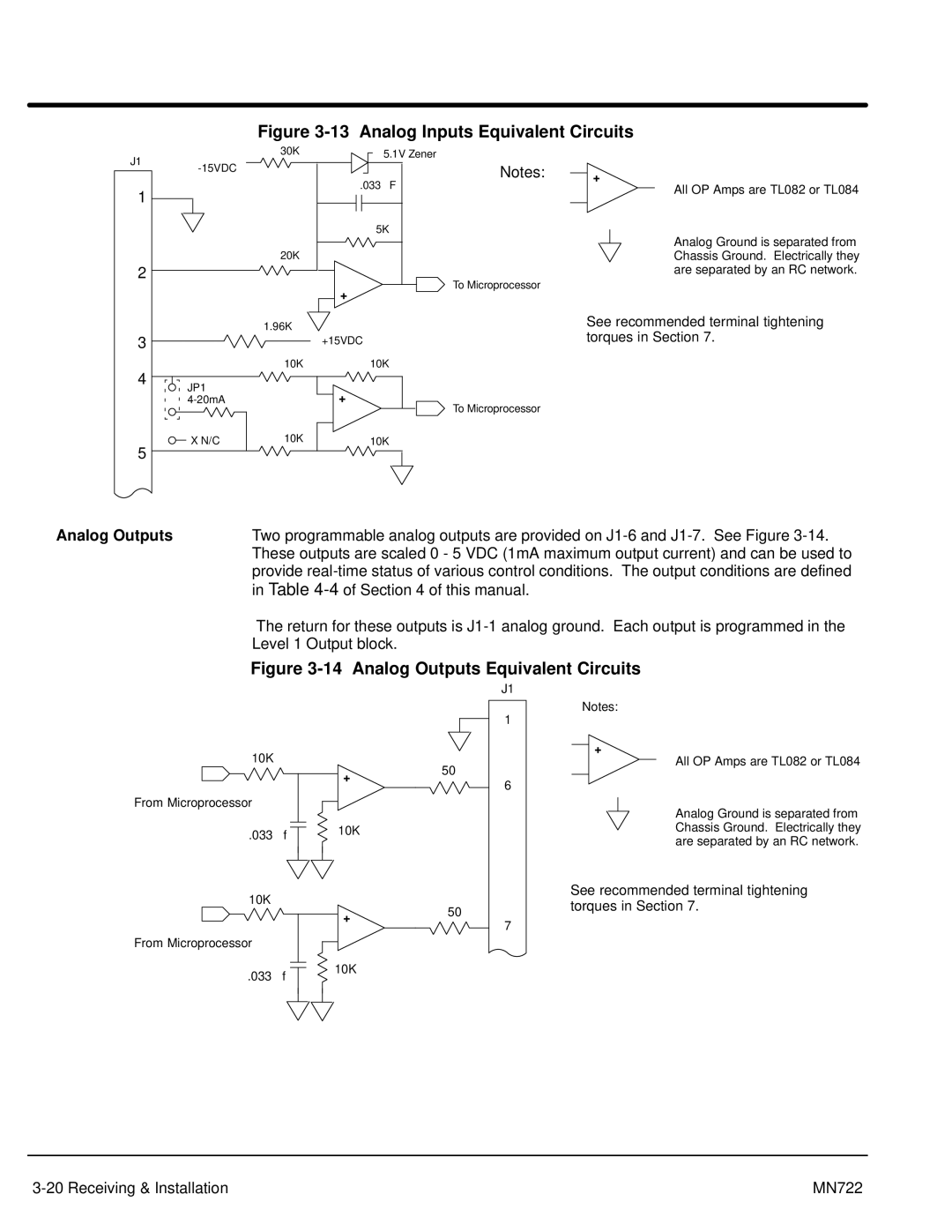
Figure 3-13 Analog Inputs Equivalent Circuits
J1
30KW | 5.1V Zener |
Notes:
+
1
2
3
4
5
JP1
500W
X N/C
| .033 mF |
| 5KW |
20KW |
|
| – |
| + |
1.96KW |
|
| +15VDC |
10KW | 10KW |
| + |
| – |
10KW | 10KW |
To Microprocessor
To Microprocessor
All OP Amps are TL082 or TL084
–
Analog Ground is separated from Chassis Ground. Electrically they are separated by an RC network.
See recommended terminal tightening torques in Section 7.
Analog Outputs | Two programmable analog outputs are provided on | ||||||||
| These outputs are scaled 0 - 5 VDC (1mA maximum output current) and can be used to | ||||||||
| provide | ||||||||
| in Table |
|
|
| |||||
| The return for these outputs is | ||||||||
| Level 1 Output block. |
|
|
|
|
|
|
| |
| Figure | ||||||||
|
|
|
|
|
| J1 |
|
|
|
|
|
|
|
|
| 1 | Notes: | ||
| 10KW |
|
|
| + |
| All OP Amps are TL082 or TL084 | ||
|
|
|
| ||||||
|
|
|
|
|
|
| |||
|
| 50W |
|
| |||||
|
|
|
| ||||||
|
| + | – | ||||||
|
|
|
| 6 |
|
|
| ||
|
| – |
|
|
|
|
| ||
From Microprocessor |
|
|
|
|
|
| Analog Ground is separated from | ||
|
|
|
|
|
| ||||
|
|
|
|
|
|
| |||
|
|
|
|
|
|
|
|
| |
| .033 mf | 10KW |
|
|
|
|
|
| Chassis Ground. Electrically they |
|
|
|
|
|
|
|
| are separated by an RC network. | |
|
|
|
|
|
|
|
|
| |
10KW |
|
| See recommended terminal tightening |
| 50W | torques in Section 7. | |
| + | ||
| 7 | ||
|
| ||
| – |
| |
From Microprocessor |
|
| |
|
|
| |
.033 mf | 10KW |
|
|
|
|
|
MN722 |