|
| Table |
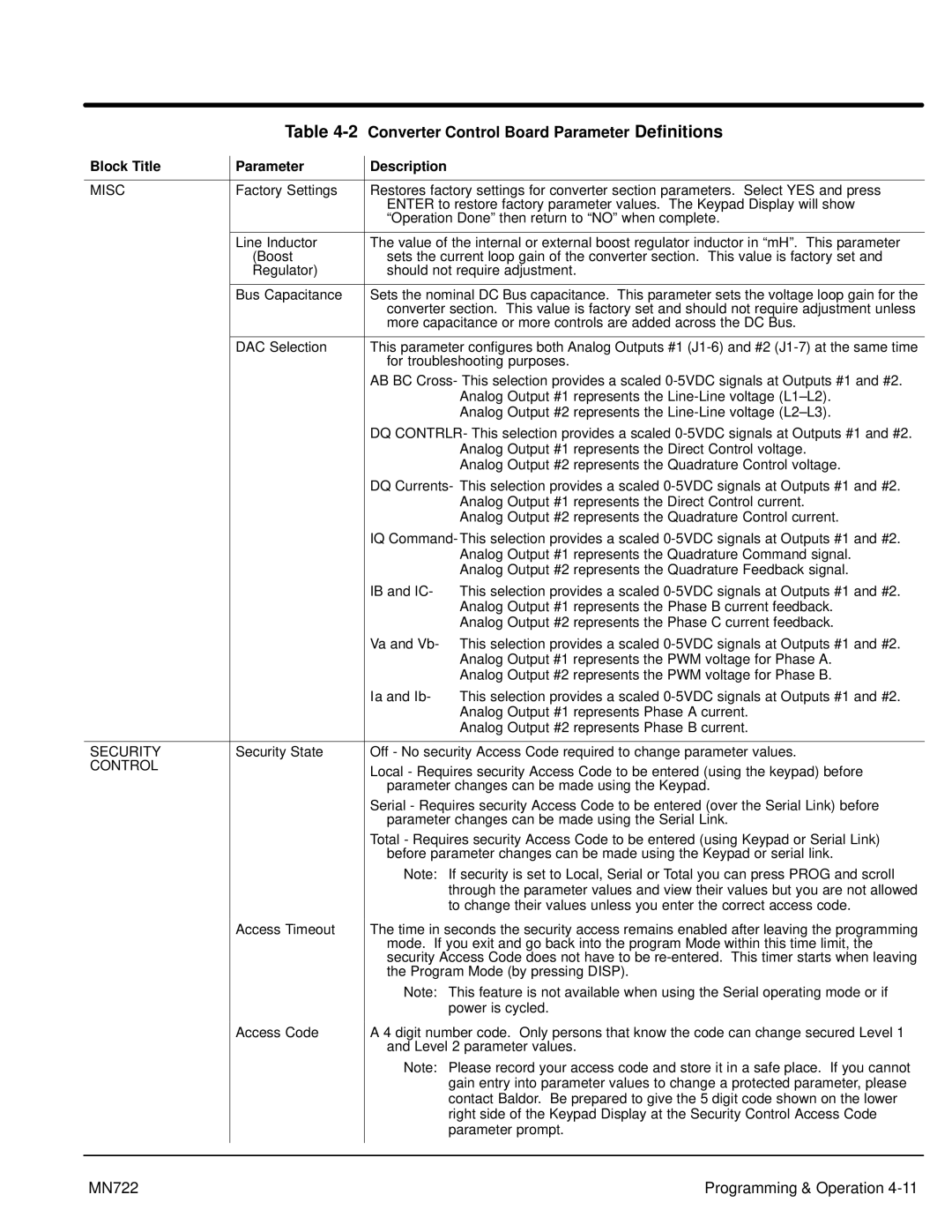
| Converter Control Board Parameter Definitions | |
Block Title |
| Parameter |
| Description |
|
|
|
| |||
|
|
|
|
| |
MISC |
| Factory Settings |
| Restores factory settings for converter section parameters. Select YES and press | |
|
|
|
| ENTER to restore factory parameter values. The Keypad Display will show | |
|
|
|
| “Operation Done” then return to “NO” when complete. | |
|
|
|
|
| |
|
| Line Inductor |
| The value of the internal or external boost regulator inductor in “mH”. This parameter | |
|
| (Boost |
| sets the current loop gain of the converter section. This value is factory set and | |
|
| Regulator) |
| should not require adjustment. | |
|
|
|
|
| |
|
| Bus Capacitance |
| Sets the nominal DC Bus capacitance. This parameter sets the voltage loop gain for the | |
|
|
|
| converter section. This value is factory set and should not require adjustment unless | |
|
|
|
| more capacitance or more controls are added across the DC Bus. | |
|
|
|
|
| |
|
| DAC Selection |
| This parameter configures both Analog Outputs #1 | |
|
|
|
| for troubleshooting purposes. | |
|
|
|
| AB BC Cross- This selection provides a scaled | |
|
|
|
|
| Analog Output #1 represents the |
|
|
|
|
| Analog Output #2 represents the |
|
|
|
| DQ CONTRLR- This selection provides a scaled | |
|
|
|
|
| Analog Output #1 represents the Direct Control voltage. |
|
|
|
|
| Analog Output #2 represents the Quadrature Control voltage. |
|
|
|
| DQ Currents- This selection provides a scaled | |
|
|
|
|
| Analog Output #1 represents the Direct Control current. |
|
|
|
|
| Analog Output #2 represents the Quadrature Control current. |
|
|
|
| IQ Command- This selection provides a scaled | |
|
|
|
|
| Analog Output #1 represents the Quadrature Command signal. |
|
|
|
|
| Analog Output #2 represents the Quadrature Feedback signal. |
|
|
|
| IB and IC- | This selection provides a scaled |
|
|
|
|
| Analog Output #1 represents the Phase B current feedback. |
|
|
|
|
| Analog Output #2 represents the Phase C current feedback. |
|
|
|
| Va and Vb- This selection provides a scaled | |
|
|
|
|
| Analog Output #1 represents the PWM voltage for Phase A. |
|
|
|
|
| Analog Output #2 represents the PWM voltage for Phase B. |
|
|
|
| Ia and Ib- | This selection provides a scaled |
|
|
|
|
| Analog Output #1 represents Phase A current. |
|
|
|
|
| Analog Output #2 represents Phase B current. |
|
|
|
|
| |
SECURITY |
| Security State |
| Off - No security Access Code required to change parameter values. | |
CONTROL |
|
|
| Local - Requires security Access Code to be entered (using the keypad) before | |
|
|
|
| ||
|
|
|
| parameter changes can be made using the Keypad. | |
|
|
|
| Serial - Requires security Access Code to be entered (over the Serial Link) before | |
|
|
|
| parameter changes can be made using the Serial Link. | |
|
|
|
| Total - Requires security Access Code to be entered (using Keypad or Serial Link) | |
|
|
|
| before parameter changes can be made using the Keypad or serial link. | |
|
|
|
| Note: If security is set to Local, Serial or Total you can press PROG and scroll | |
|
|
|
|
| through the parameter values and view their values but you are not allowed |
|
|
|
|
| to change their values unless you enter the correct access code. |
|
| Access Timeout |
| The time in seconds the security access remains enabled after leaving the programming | |
|
|
|
| mode. If you exit and go back into the program Mode within this time limit, the | |
|
|
|
| security Access Code does not have to be | |
|
|
|
| the Program Mode (by pressing DISP). | |
|
|
|
| Note: This feature is not available when using the Serial operating mode or if | |
|
|
|
|
| power is cycled. |
|
| Access Code |
| A 4 digit number code. Only persons that know the code can change secured Level 1 | |
|
|
|
| and Level 2 parameter values. | |
|
|
|
| Note: Please record your access code and store it in a safe place. If you cannot | |
|
|
|
|
| gain entry into parameter values to change a protected parameter, please |
|
|
|
|
| contact Baldor. Be prepared to give the 5 digit code shown on the lower |
|
|
|
|
| right side of the Keypad Display at the Security Control Access Code |
|
|
|
|
| parameter prompt. |
|
|
|
|
|
|
|
|
|
|
|
|
MN722 | Programming & Operation |