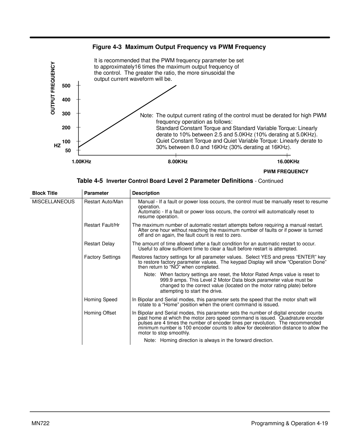
Figure 4-3 Maximum Output Frequency vs PWM Frequency
FREQUENCY
It is recommended that the PWM frequency parameter be set to approximately16 times the maximum output frequency of the control. The greater the ratio, the more sinusoidal the output current waveform will be.
OUTPUT
HZ
500
400
300
200
100
50
1.00KHz
Note: The output current rating of the control must be derated for high PWM frequency operation as follows:
Standard Constant Torque and Standard Variable Torque: Linearly derate to 10% between 2.5 and 5.0KHz (10% derating at 5.0KHz). Quiet Constant Torque and Quiet Variable Torque: Linearly derate to 30% between 8.0 and 16KHz (30% derating at 16KHz).
8.00KHz | 16.00KHz |
PWM FREQUENCY
Table 4-5 Inverter Control Board Level 2 Parameter Definitions - Continued
Block Title | Parameter | Description |
|
|
|
MISCELLANEOUS | Restart Auto/Man | Manual - If a fault or power loss occurs, the control must be manually reset to resume |
|
| operation. |
|
| Automatic - If a fault or power loss occurs, the control will automatically reset to |
|
| resume operation. |
| Restart Fault/Hr | The maximum number of automatic restart attempts before requiring a manual restart. |
|
| After one hour without reaching the maximum number of faults or if power is turned |
|
| off and on again, the fault count is rest to zero. |
| Restart Delay | The amount of time allowed after a fault condition for an automatic restart to occur. |
|
| Useful to allow sufficient time to clear a fault before restart is attempted. |
| Factory Settings | Restores factory settings for all parameter values. Select YES and press “ENTER” key |
|
| to restore factory parameter values. The keypad Display will show “Operation Done” |
|
| then return to “NO” when completed. |
|
| Note: When factory settings are reset, the Motor Rated Amps value is reset to |
|
| 999.9 amps. This Level 2 Motor Data block parameter value must be |
|
| changed to the correct value (located on the motor rating plate) before |
|
| attempting to start the drive. |
| Homing Speed | In Bipolar and Serial modes, this parameter sets the speed that the motor shaft will |
|
| rotate to a “Home” position when the orient command is issued. |
| Homing Offset | In Bipolar and Serial modes, this parameter sets the number of digital encoder counts |
|
| past home at which the motor zero speed command is issued. Quadrature encoder |
|
| pulses are 4 times the number of encoder lines per revolution. The recommended |
|
| minimum number is 100 encoder counts to allow for deceleration distance to allow the |
|
| motor to stop smoothly. |
|
| Note: Homing direction is always in the forward direction. |
|
|
|
MN722 | Programming & Operation |