Bipolar Speed and Torque Mode Connections
Provides bipolar speed or torque control. Also, you may store up to four (4) complete sets of operating parameters. This is important if you wish to store and use different acceleration rates, speed commands, jog speeds or to store tuning parameter values for different motors etc. The opto inputs can be switches as shown in Figure
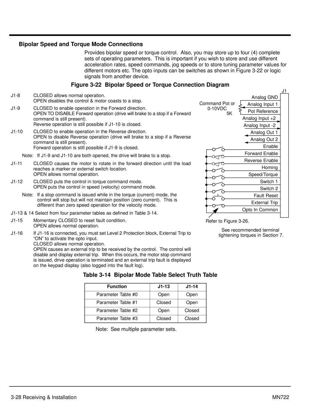
Figure 3-22 Bipolar Speed or Torque Connection Diagram
OPEN disables the control & motor coasts to a stop.
OPEN TO DISABLE Forward operation (drive will brake to a stop if a Forward command is still present).
Reverse operation is still possible if
OPEN to disable Reverse operation (drive will brake to a stop if a Reverse command is still present).
Forward operation is still possible if
Note: If
OPEN allows normal operation.
Note: If a stop command is issued while in the torque (current) mode, the control will stop but will not maintain position (zero current). This is different than zero speed operation for the velocity mode.
|
| J1 | |
| Analog GND | 1 | |
Command Pot or | Analog Input 1 | ||
2 | |||
Pot Reference | |||
5KW | 3 | ||
Analog Input +2 | |||
| 4 | ||
| Analog Input | ||
| 5 | ||
| Analog Out 1 | ||
| 6 | ||
| Analog Out 2 | ||
| 7 | ||
| Enable | ||
| 8 | ||
| Forward Enable | ||
| 9 | ||
| Reverse Enable | ||
| 10 | ||
| Homing | 11 | |
| Speed/Torque | ||
| 12 | ||
| Switch 1 | 13 | |
| Switch 2 | 14 | |
| Fault Reset | 15 | |
| External Trip | 16 | |
| Opto In Common | 17 |
Refer to Figure
See recommended terminal tightening torques in Section 7.
Table 3-14 Bipolar Mode Table Select Truth Table
Function |
|
|
|
|
|
Parameter Table #0 | Open | Open |
|
|
|
Parameter Table #1 | Closed | Open |
|
|
|
Parameter Table #2 | Open | Closed |
|
|
|
Parameter Table #3 | Closed | Closed |
|
|
|
Note: See multiple parameter sets.
MN722 |